Table of Contents
Advertisement
Quick Links
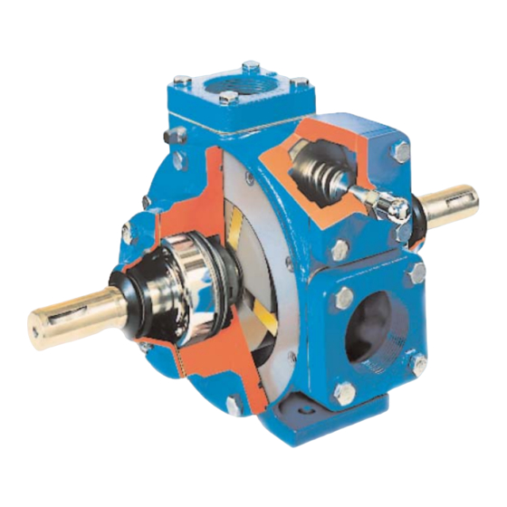
BLACKMER TRUCK PUMPS
INSTALLATION OPERATION AND MAINTENANCE INSTRUCTIONS
MODELS: TXD1220A, 1225A, 1230A
Numbers in parentheses following individual parts
indicate reference numbers on Blackmer Parts Lists
201-D02, 201-D03 and 201-D04.
Blackmer pump manuals and parts lists may be
obtained from Blackmer's website (www.blackmer.com)
or by contacting Blackmer Customer Service.
This is a SAFETY ALERT SYMBOL.
When you see this symbol on the product, or in the
manual, look for one of the following signal words and be
alert to the potential for personal injury, death or major
property damage
Warns of hazards that WILL cause serious personal injury,
death or major property damage.
Warns of hazards that CAN cause serious personal injury,
death or major property damage.
Warns of hazards that CAN cause personal injury
or property damage.
NOTICE:
Indicates special instructions which are very
important and must be followed.
TABLE OF CONTENTS
Technical Data ....................................................... 2
Initial Pump Start Up Information ........................... 2
Pre-Installation Cleaning ........................................ 3
Location and Piping ............................................... 3
Truck Mounting ...................................................... 3
Pump Drive ............................................................ 3
Pump Rotation ....................................................... 4
To Change Pump Rotation .................................... 4
Pre-Start Up Check List ......................................... 5
Start Up Procedures .............................................. 5
Pump Speed .......................................................... 5
Reverse Rotation ................................................... 5
Flushing the Pump ................................................. 6
Pump Relief Valve ................................................. 6
Relief Valve Setting and Adjustment...................... 6
Strainers ................................................................ 7
Lubrication ............................................................. 7
Vane Replacement ................................................ 8
Pump Disassembly ................................................ 8
Pump Assembly ..................................................... 9
TROUBLE SHOOTING ......................................
SAFETY DATA
Blackmer Truck Pumps MUST only be installed in systems,
which have been designed by qualified engineering
personnel.
local and national regulations and safety standards.
This manual is intended to assist in the installation and
operation of the Blackmer truck pumps, and MUST be kept
with the pump.
Pump service shall be performed by qualified technicians
ONLY.
Service shall conform to all applicable local and
national regulations and safety standards.
Thoroughly review this manual, all instructions and hazard
warnings, BEFORE performing any work on the pump.
Maintain ALL system and pump operation and hazard
warning decals.
961680
INSTRUCTIONS NO. 201-D00
Section
Effective
Replaces
NOTICE:
The system MUST conform to all applicable
201
Jan 2014
Aug 2010
Page
10
Advertisement
Table of Contents

Subscribe to Our Youtube Channel
Related Manuals for Dover PSG Blackmer TXD1200 Series


Summary of Contents for Dover PSG Blackmer TXD1200 Series
-
Page 1: Table Of Contents
961680 BLACKMER TRUCK PUMPS INSTRUCTIONS NO. 201-D00 Section INSTALLATION OPERATION AND MAINTENANCE INSTRUCTIONS Effective Jan 2014 MODELS: TXD1220A, 1225A, 1230A Replaces Aug 2010 TABLE OF CONTENTS Page PUMP DATA Technical Data ............2 Initial Pump Start Up Information ......2 INSTALLATION Pre-Installation Cleaning ........ -
Page 2: Pump Data
SAFETY DATA Failure to set the vehicle emergency Disconnecting fluid or pressure brake and chock wheels before containment components during pump performing service can cause severe operation can cause serious personal personal injury or property damage. injury, death or major property damage Hazardous pressure Hazardous pressure can cause personal... -
Page 3: Installation
INSTALLATION NOTICE: PUMP DRIVE Blackmer truck pumps must only be installed in systems The pump may be driven by a power take-off through designed by qualified engineering personnel. System universal joints. When using universal joints, a splined slip design must conform with all applicable regulations and joint, properly lubricated, must be used on the connecting codes and provide warning of all system hazards. -
Page 4: Pump Rotation
INSTALLATION Hydraulic Drive TO CHANGE PUMP ROTATION The TXD1200 series pump models are equipped with a The pump may also be driven hydraulically. Hydraulic motors double ended rotor and shaft, enabling them to be driven from need to be well supported with their shafts parallel to the either shaft end. -
Page 5: Operation
OPERATION START UP PROCEDURES NOTICE: Consult the "General Pump Troubleshooting" section of Pumps operating against a closed this manual if difficulties during start up are experienced. valve can cause system failure, personal injury and property damage 1. Ensure that appropriate valves are open in the inlet and Hazardous pressure can cause personal discharge lines. -
Page 6: Flushing The Pump
OPERATION FLUSHING THE PUMP RELIEF VALVE SETTING AND ADJUSTMENT NOTICE: If flushing fluid is to be left in the pump for an extended time, it must be a lubricating, non-corrosive fluid. If a corrosive, non-lubricating fluid is used, it must be Relief valve cap is exposed to pumpage flushed from the pump immediately. -
Page 7: Maintenance
MAINTENANCE Failure to set the vehicle emergency Disconnecting fluid or pressure brake and chock wheels before containment components during pump performing service can cause severe operation can cause serious personal personal injury or property damage. injury, death or major property damage Hazardous pressure Hazardous pressure can cause personal... -
Page 8: Vane Replacement
MAINTENANCE VANE REPLACEMENT 4. Remove locknuts and lockwashers (24A, 24B): NOTICE: a. Bend up the engaged lockwasher tang and remove Maintenance shall be performed by qualified technicians setscrew (24C). Rotate the locknut counterclockwise only, following the appropriate procedures and warnings to remove it from the shaft. -
Page 9: Pump Assembly
MAINTENANCE PUMP ASSEMBLY 10. Rotate the shaft by hand to engage the mechanical seal drive tangs, and to test for binding or tight spots. If the Before reassembling the pump, inspect all component rotor does not turn freely, lightly tap the rims of the heads parts for wear or damage, and replace as required. -
Page 10: Troubleshooting
MAINTENANCE 12. Inspect the grease seal (104) for wear or damage and 18. RELIEF VALVE ASSEMBLY replace as required. Grease the outside diameter of the If the pump is equipped with a Blackmer air valve, refer to grease seal and push it into the bearing cover (27 or 27A) setting and adjustment procedures in Blackmer Air Valve with the lip of the seal inward. - Page 11 TROUBLESHOOTING continued Pump speed too low. Suction valves not fully open. Air leaks in the suction line. Excessive restriction in the suction line (i.e.: undersized piping, too many elbows & Reduced Capacity fittings, clogged strainer, etc.). Damaged or worn parts. Excessive restriction in discharge line causing partial flow through the relief valve.
- Page 12 Stainless Steel Sliding Vane Pumps Sliding Vane Pumps: 5 to 2200 GPM 1 to 265 GPM: Acids, Brines, Sugars, Syrups, Refined Fuels, Liquefied Gases, Solvents,Process Beer, Beet Juice, Cider, Flavor Extracts, etc. ® System One Centrifugal Pumps Magnetic Drive Pumps 10 to 7500 GPM;...
Need help?
Do you have a question about the PSG Blackmer TXD1200 Series and is the answer not in the manual?
Questions and answers