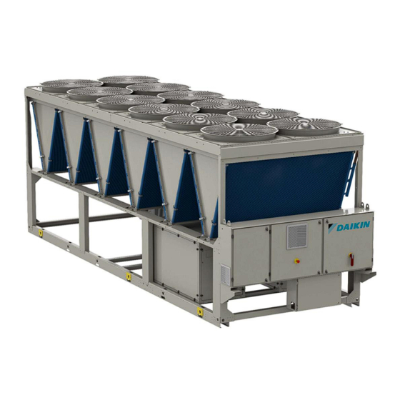
Sign In
Upload
Manuals
Brands
Daikin Manuals
Chiller
EWAH TZ D Series
Daikin EWAH TZ D Series Manuals
Manuals and User Guides for Daikin EWAH TZ D Series. We have
1
Daikin EWAH TZ D Series manual available for free PDF download: Installation, Operation And Maintenance Manual
Daikin EWAH TZ D Series Installation, Operation And Maintenance Manual (53 pages)
Air Cooled Chiller with Inverter Driven Screw compressor
Brand:
Daikin
| Category:
Chiller
| Size: 2.57 MB
Table of Contents
Table of Contents
2
Fig. 1- Refrigerant Circuit Diagram (P&ID) - MONO Circuit Units
4
Table 1 - Legend Refrigerant Circuit Diagram (P&ID) - MONO Circuit Units
5
Fig. 2 - Refrigerant Circuit Diagram (P&ID) - DUAL Circuit Units
6
Table 2 - Legend Refrigerant Circuit Diagram (P&ID) - DUAL Circuit Units
7
Fig. 3 - Hydronic Free Cooling P&ID
8
Table 3 - Legend Hydronic Free Cooling P&ID
8
Fig. 4. - Description of the Labels Applied to the Electrical Panel
9
Table 4 - Units PS and TS
9
Table 5 - Label Identification
9
Introduction
10
Precautions against Residual Risks
10
Description
11
Information about R1234Ze(E) Refrigerant
11
Table 6 - Physical Characteristics of Refrigerant R1234Ze(E)
11
Information about Installation
12
Table 7 - R1234Ze(E) Ignition and Max Temperatures
12
Table 8 - R1234Ze(E) LFL Value
13
Receiving the Unit
14
Operating Limits
15
Storage
15
Operation
15
Table 9 - Units Environmental Conditions
15
Fig. 5 - EWAH-TZD Blue Unit Envelope
16
Fig. 6 - EWAH-TZD Silver Unit Envelope
16
Fig. 7 - EWAH-TZD Gold and Platinum Unit Envelope
17
Fig. 8 - EWAD-TZD Blue Unit Envelope
17
Fig. 9 - EWAD-TZD Silver Unit Envelope
18
Fig. 10 - EWAD-TZD Gold and Platinum Unit Envelope
18
Fig. 11 - EWAS-TZD Blue Unit Envelope
19
Fig. 12 - EWAS-TZD Silver Unit Envelope
20
Fig. 13 - EWAS-TZD Gold and Platinum Unit Envelope
20
Fig. 14 - EWFH-TZD Blue and Silver Unit Envelope
21
Fig. 15 - EWFH-TZD Gold and Platinum Unit Envelope
21
Corrective Factors
22
Fig. 16 - EWFD-TZD Blue and Silver Unit Envelope
22
Fig. 17 - EWFD-TZD Gold and Platinum Unit Envelope
22
Table 10 - Altitude Correction Factor
23
Table 11 - Minimum Percentage of Glycol in Case of Low Ambient Temperature
23
Mechanical Installation
24
Safety
24
Safety Devices
24
Fig. 18 - Indirect Vented Closed System
24
Handling and Lifting Instructions
25
Fig. 19 - Lifting Instructions
27
Positioning and Assembly
28
Minumum Space Requirements
28
Fig. 20 - Unit Levelling
28
Fig. 21 - Minimum Clearance Requirements
29
Noise and Sound Protection
31
Water Circuit for Unit Connection
31
Water Piping
31
Fig. 22. - Multiple Chiller Installation
31
Fig. 23 - Anti-Vibration Elements (Supplied as Optional)
31
4.6.2 Kit Pump Option
32
Fig. 24- Hydraulic Diagram (Opt. 78-79-80-81/120E-120F-120G-120H)
32
Table 12 - Legend Hydraulic Diagram
32
4.6.3 Flow Switch Option Installation
33
4.6.4 Heat Recovery Option
33
Water Treatment
33
Hydronic Free Cooling System
33
Introduction and System Description (P&ID)
33
Table 13 - Acceptable Water Quality Limits
33
Fig. 25- Hydronic Free Cooling P&ID
35
Table 14 - Legend Hydronic Free Cooling P&ID
35
Coolant Quality Requirements
36
First Operations at Unit Commissioning Start
36
Table 15 - Free Cooling Application Coolant Quality Requirements for MCH Coils
36
Free Cooling Purge Valve Related
37
Operations in Case of Failure
37
Evaporator and Heat Recovery Exchangers Anti-Freeze Protection
37
Electrical Installation
38
General Specifications
38
Electrical Supply
38
Electric Connections
38
Cable Requirements
39
Phase Unbalance
39
Table 16- Table 1 of EN60204-1 Point 5.2
39
Electrical Panel Label Description
40
Fig. 26- Description of Labels Applied on the Electrical Panel Small
40
Fig. 27- Description of Labels Applied on the Electrical Panel Medium
41
Fig. 28- Description of Labels Applied on the Electrical Panel Large
41
Operator's Responsibilities
42
Maintenance
43
Routine Maintenance
43
Table 18- General Maintenance Table
43
Table 19 - Standard Routine Maintenance Plan
44
Unit Maintenance and Cleaning
45
Table 20 - Routine Maintenance Plan for Critical Application And/Or Highly Aggressive Environment
45
Microchannel Coil Maintenance
46
Inverter Capacitors
46
Table 21 - Inverter Sizes
47
Service and Limited Warranty
48
First Start-Up Checks
49
Table 22 - Checks to be Performed before Starting the Unit
49
10 Periodic Checks and Commissioning of Pressure Equipment
50
11 Important Information about the Refrigerant Used
51
11.1 Factory and Field Charged Units Instructions
51
Fig. 29 - Refrigerant Charge Label
51
12 Dismission and Disposal
52
Advertisement
Advertisement
Related Products
Daikin EWAQ210DAYN
Daikin EWAQ~G-SS
Daikin EWAQ-F
Daikin EWAQ025CAW
Daikin EWAQ011ACV3
Daikin EWAPC18AJYNN
Daikin EWAD150MBYNN1
Daikin EWAQ006AAV3P
Daikin EWAQ007AAV3P
Daikin ERAD-E EWAD210E-SS Series
Daikin Categories
Air Conditioner
Heat Pump
Remote Control
Chiller
Fan
More Daikin Manuals
Login
Sign In
OR
Sign in with Facebook
Sign in with Google
Upload manual
Upload from disk
Upload from URL