CAME BY-3500T Installation Manual
Sliding-gate operators
Hide thumbs
Also See for BY-3500T:
- Installation manual (25 pages) ,
- Quick setup manual (12 pages) ,
- Manual (17 pages)
Table of Contents
Advertisement
Quick Links
Advertisement
Table of Contents

Related Manuals for CAME BY-3500T


Summary of Contents for CAME BY-3500T
- Page 1 FA01731-EN Sliding-gate operators BY-3500T INSTALLATION MANUAL English...
- Page 3 (railway carriage, containers, closed vehicles). • If the product malfunctions, stop using it and contact customer services at https://www.came.com/global/en/ contact-us or via the telephone number on the website. • The manufacture date is provided in the production batch printed on the product label.
-
Page 4: Dismantling And Disposal
DISMANTLING AND DISPOSAL CAME S.p.A. employs an Environmental Management System at its premises. This system is certified and compliant with the UNI EN ISO 14001 standard to ensure that the environment is respected and safeguarded. Please continue safeguarding the environment. At CAME we consider it one of the fundamentals of our operating and market strategies. -
Page 5: Intended Use
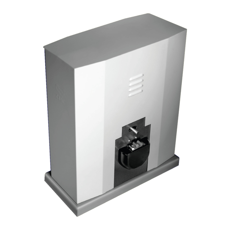
PRODUCT DATA AND INFORMATION This symbol shows which parts to read carefully. This symbol shows which parts describe safety issues. This symbol shows what to tell users. The measurements, unless otherwise stated, are in millimetres. Description 001BY-3500T BY3500T - Operator with 400 V AC three-phase motor, complete with control board and mechanical limit switches for sliding gates up to 3500 kg in weight and 17 m in length. - Page 6 Control board All connections are protected by quick fuses. For the system to work properly, before fitting any plug-in card, DISCONNECT THE MAIN POWER SUPPLY and remove any batteries. Before working on the control panel, disconnect the mains power supply and remove the batteries, if any. Terminal block for connecting the transformer and contactors Terminal block for connecting the soft starter Accessories fuse...
- Page 7 (**) The average product life specified should be understood purely as an indicative estimate. It applies to normal usage conditions and where the product has been installed and maintained in compliance with the instructions provided in the CAME technical manual. The average product life is also affected, including significantly, by other variables such as, but not limited to, climatic and environmental conditions.
-
Page 8: Operating Cycles
The operating cycle calculation considers a gate that is of standard length (the sliding part), professionally installed, free of any mechanical issues and/or accidental friction points, and measured at an ambient temperature of 20°C, as stated in EN standard 60335-2-103. MODELS BY-3500T Cycles/hour (no.) Standard length (m) -
Page 9: Installation
INSTALLATION The following illustrations are examples only. The space available for fitting the operator and accessories varies depending on the area where it is installed. It is up to the installer to find the most suitable solution. The drawings show an operator fitted on the left. Preliminary operations Dig a hole for the foundation frame. - Page 10 Fasten the anchoring clamps to the plate by using the supplied screws, washers and nuts. Fit the anchoring plate in the iron cage. The tubes must pass through the existing holes. Position the anchoring plate, taking note of the measurements shown in the drawing. If the gate does not have a rack, proceed with the installation.
- Page 11 Remove the nuts from the screws. Insert the electrical cables into the tubes until they protrude by about 600 mm. Setting up the operator Remove the front cover. Remove the side screws. Remove the cabinet. Place the operator on top of the anchoring plate. The electrical cables must pass under the operator foundation frame Lift the operator by 5-10 mm from the plate by adjusting the threaded feet, to allow for any adjustments that may need to be made between the rack and pinion.
- Page 12 Fastening the rack Release the operator. Rest the rack on the pinion. Weld or fasten the rack to the gate along its entire length. To assemble the rack modules, use an extra piece and rest it under the joint, then fasten it in place using two clamps.
- Page 13 Adjusting the pinion-rack coupling Open and close the gate manually. Adjust the pinion-rack coupling distance using the threaded feet (vertical adjustment) and the holes (horizontal adjustment). The weight of the gate must not bear down upon the operator. Fastening the operator in place Only fasten the operator after adjusting the pinion-rack coupling.
- Page 14 Determining the travel end points with mechanical limit switches Open the gate. Insert the opening limit-switch tab in the rack. The spring must trigger the microswitch. Fasten the opening limit-switch tab using the grub screws supplied. ~ 20 Close the gate. Insert the closing limit-switch tab in the rack.
-
Page 15: Electrical Connections
ELECTRICAL CONNECTIONS Passing the electrical cables Connect all wires and cables in compliance with the law. The electrical cables must not touch any parts that may overheat during use (such as the motor and transformer). Use cable glands to connect the devices to the control panel. One of these must be used exclusively for the power supply cable. Reversal of the gate opening time The operator is designed to be fitted on the left. -
Page 16: Power Supply
Power supply Make sure the mains power supply is disconnected during all installation procedures. Before working on the control panel, cut off the mains power supply. Connecting to the mains (400 V AC - three-phase - 50/60 Hz) Power supply output for accessories The output normally delivers 24 V AC. -
Page 17: Command And Control Devices
Command and control devices STOP button (NC contact) This stops the operator and excludes automatic closing. Use a control device to resume movement. See function [Total stop]. When the contact is being used, it must be activated during programming. Control device (NO contact) Open command When the [Hold-to-run] function is active, a control device must be set to OPEN. -
Page 18: Signalling Devices
Signalling devices Additional light It increases the light in the manoeuvring area. Flashing beacon It flashes when the operator opens and closes. Operator status warning light (OPEN) The operator is open. Operator status warning light (CLOSED) The operator is closed. Safety devices During programming, configure the type of action that must be performed by the device connected to the input. - Page 19 DIR / DELTA-S photocells Standard connection Connection with safety test TX 2 TX 2 2 TX C NC 2 TX C NC DXR/DLX photocells Standard connection Connection with safety test 10 11 OUT 10 11 OUT 10 11 SY 10 11 SY DFWN sensitive edge C NO NC DFWN...
-
Page 20: Soft Start
SOFT START The maximum power of the motor to be connected to the soft starter must not exceed the maximum power of the board. Gearmotor input ① + 24 V DC power supply connection Gearmotor output ② GND power supply connection Commands and soft starter power supply terminal block connections ③... -
Page 21: Functions Menu
Functions menu DIP-switch 1 ON Automatic closure Activate automatic closing. The function does not work if any of the safety devices are triggered when an obstacle is detected, or after a complete stop, or during a power outage. To adjust the automatic closing time, see [Settings]. DIP-switch 2 ON Sequential Enable sequential command from control device (2-7) and transmitter. - Page 22 CX input Associate a function with the CX input. If the devices are not connected to the 2-CX terminal, set DIP switch 8 to ON. DIP 8 OFF CX = C2 DIP 9 OFF Reclose while opening (Photocells) DIP-switch 15 OFF DIP 8 OFF CX = r7 DIP 9 OFF...
- Page 23 ENABLING THE RADIO CONTROL Electrical connections Before working on the control panel, disconnect the mains power supply and remove the batteries, if any. Fit an AF card to the control board using the AF connector. Connect the RG58 cable to the terminals. Connect up the electrics for the devices and accessories.
-
Page 24: Final Operations
FINAL OPERATIONS... - Page 25 PAIRED OPERATION Two connected operators are controlled with one command. Electrical connections Reverse the SLAVE operator motor and limit switches phases. Connect the two electronic boards. The devices and accessories must be connected to the control board which will be set as the MASTER. For information on connecting the electrics for the devices and accessories, please see the “ELECTRICAL CONNECTIONS”...
- Page 26 Saving users All save user operations must be performed only on the control board set as the MASTER. Operating modes MASTER OPENING command Only the operator configured as the MASTER will open. The open gate button on the transmitter must be stored on channel CH1 on the gearmotor. Open command Both the MASTER and SLAVE operator open.
- Page 28 AFFIX THE PRODUCT LABEL FROM THE BOX HERE CAME S.p.A. Via Martiri della Libertà, 15 31030 Dosson di Casier Treviso – Italy Tel. (+39) 0422 4940 Fax (+39) 0422 4941 info@came.com - www.came.com...
Need help?
Do you have a question about the BY-3500T and is the answer not in the manual?
Questions and answers