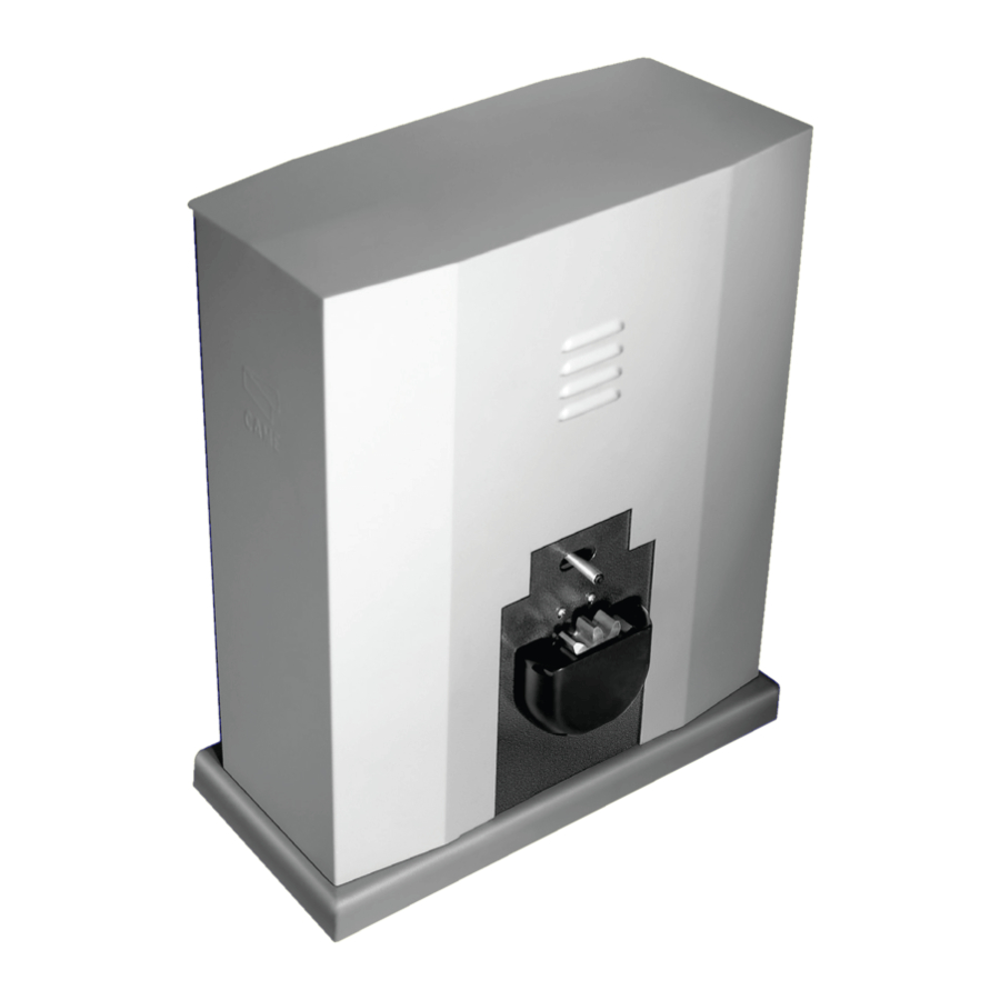
CAME BY-3500T Installation Manual
Sliding gate operators
Hide thumbs
Also See for BY-3500T:
- Installation manual (29 pages) ,
- Quick setup manual (12 pages) ,
- Manual (17 pages)

Related Manuals for CAME BY-3500T


Summary of Contents for CAME BY-3500T
- Page 1 Sliding gate operators FA01296-EN BY-3500T BY-3500T INSTALLATION MANUAL EN English...
- Page 3 GENERAL PRECAUTIONS FOR INSTALLERS Important safety instructions. Follow all of these instructions. Improper installation can cause serious bodily harm. Before continuing, also read the general precautions for users. Use this product only for its specifically intended use. Any other use is hazardous. The manufacturer can not be held liable for any damage caused by improper, unreasonable, and erroneous use.
- Page 4 Any residual risks must be indicated clearly with proper signage affixed in visible areas. All of which must be explained to end users. Fit, in plain sight, the machine's ID plate when the installation is complete. If the power-supply cable is damaged, it must be immediately replaced by the manufacturer or by an authorized technical assistance center, or in any case, by qualified staff, to prevent any risk.
-
Page 5: Intended Use
PRODUCT DATA AND INFORMATION Legend This symbol shows which parts to read carefully. This symbol shows which parts describe safety issues This symbol shows which parts to tell users about. The measurements, unless otherwise stated, are in millimeters. Description Operator complete with control board and mechanical end stops for sliding gates up to 3.500 kg in weight and 17 m in length. Intended use Ideal solution for applying to large gates Any installation and/or use other than that specified in this manual is forbidden. - Page 6 Control board All wiring connections are quick-fuse protected. For the system to work properly, before fitting any plug-in card, you MUST CUT OFF THE MAIN POWER SUPPLY and remove any batteries. Before working on the control panel, cut off the mains power supply and remove the batteries, if any. 1 - DIP for programming 7 - Alert LED 2 -Control board fuse...
-
Page 7: Technical Data
Dimensions Limits to use MODELS BY-3500T Pinion module Maximum gate-leaf length (m) Maximum gate-leaf weight (kg) 3500 Technical data MODELS BY-3500T Power supply (V - 50/60 Hz) 230/ 400 V AC THREE PHASE Motor power supply (V) 230/ 400 V AC THREE PHASE... -
Page 8: Operating Cycles
The work cycles calculation is for a gate with standard reference length of the sliding part, that is professionally installed, free of any mechanical issues and/or accidental friction points, and measured at 20° C, as stated in EN Standard 60335- 2-103. MODELS BY-3500T Cycles/hour (no.) Standard reference length(m) Cable types and minimum thicknesses CABLE LENGTH (m) <... -
Page 9: Installation
INSTALLATION The following illustrations are just examples, as the space available for fitting the operator and accessories varies depending on the area where it is installed. The drawings show an operator fitted on the left. Preliminary operations Dig a hole for the foundation frame. Set up the corrugated tubes needed for the wiring coming out of the junction pit. - Page 10 Fasten the anchoring clamps to the plate by using the supplied screws, washers and nuts. Fit the anchoring plate into the iron cage. The tubes must run through the existing holes. Position the anchoring plate respecting the measures shown on the drawing. If the gate does not have the rack, proceed with the installation.
- Page 11 Remove the nuts from the bolts. Fit the electric cables into the tubes so that they come out about 600 mm. Setting up the operator 1 Remove the front cover. 2 Remove the side screws. 3 Remove the cabinet. Place the operator on top of the anchoring plate. The electric cables must pass under the operator case Lift the gearmotor by 5 to 10 mm from the plate by adjusting the threaded steel feet to allow any subsequent adjustments between pinion and rack.
- Page 12 Fastening the rack 1 Release the operator. 2 Rest the rack above the gearmotor. 3 Weld or fasten the rack to the gate along its entire length. To assemble the rack modules, use an extra piece and rest it under the joint, then fasten it using two clamps.
- Page 13 Adjusting the pinion-rack coupling Manually open and close the gate. Adjust the pinion-rack coupling distance using the threaded feet (vertical adjustment) and the holes (horizontal adjustment). The weight of the gate must not bear down upon the operator.
-
Page 14: Fastening The Operator
Fastening the operator Proceed with the fastening only after adjusting the pinion-rack coupling. Establishing the travel end points with mechanical limit-switches Open the gate. Insert the opening limit switch fin on the rack. The spring must trigger the microswitch. Fasten the opening limit switch fin using the headless screws (supplied). ~ 20 Close the gate. -
Page 15: Electrical Connections
ELECTRICAL CONNECTIONS Electric cables passage Connect all wires and cables in compliance with the law. The electrical cables must not touch any parts that may overheat during use (such as the motor and the transformer). Use cable glands to connect the devices to the control panel. One of these must be intended exclusively for the power supply cable. Reversal of the gate opening time The operator is designed to be fitted on the left. -
Page 16: Input Voltage
Input voltage Make sure the mains power supply is disconnected during all installation procedures. Before working on the control panel, cut off the mains power supply and remove the batteries, if any. Operator with 400 V AC three-phase power supply The operator is designed to be powered at 400 V AC three-phase. -
Page 17: Signalling Devices
Signalling devices 1 Additional light Increases illumination in the maneuvering area. E-EX contact maximum capacity 230 V AC - 60 W 2 Additional flashing light It flashes during the operator opening and closing phases. E-E1 contact maximum capacity 230 V AC - 25 W E4-10 contact maximum capacity 24 V AC - 45 W 3 Operator status warning light It indicates the open operator position. -
Page 18: Safety Devices
Safety devices During programming, configure the type of action that must be performed by the device connected to the input. Connect the safety devices to the C1 and/or CX inputs. If contacts C1 and/or CX are not used they must be deactivated during programming. DELTA photocells DELTA photocells Standard connection... -
Page 19: Selecting The Functions
PROGRAMMING Selecting the functions DIP-switch 1 ON AUTOMATIC CLOSING function DIP-switch 2 ON OPEN-STOP-CLOSE-STOP function from control device and from transmitter DIP-switch 2 OFF OPEN-CLOSE function from control device and from transmitter DIP-switch 3 ON ONLY OPEN function from transmitter DIP-switch 4 ON HOLD-TO-RUN function DIP-switch 5 ON... -
Page 20: Adjusting The Functions
Adjusting the functions + T.C.A - + AP.PARZ. - T.C.A. TRIMMER Setting the automatic closing time from 1 second to 120 seconds. PART.OP. TRIMMER Setting the partial opening time from 1 second to 14 seconds. Enabling the radio control 1 Connect the RG58 cable to the terminals. Connect the accessory, if present, to B1-B2 (NO contact). -
Page 21: Final Operations
FINAL OPERATIONS... - Page 22 COMBINED OPERATION Single command of two connected operators. Electrical connections 1 Reverse the SLAVE operator motor and limit switches phases. The devices and accessories must be connected to the control board which will be set as MASTER. For electrical connections of the devices and accessories, see the ELECTRICAL CONNECTIONS chapter. 2 Connect the two electronic boards.
-
Page 24: Dismantling And Disposal
DISMANTLING AND DISPOSAL CAME S.p.A. employs an Environmental Management System at its premises. This system is certified and compliant with the UNI EN ISO 14001 regulation standard to ensure that the environment is respected and safeguarded. Please continue safeguarding the environment. At CAME we consider it one of the fundamentals of our operating and market strategies.
Need help?
Do you have a question about the BY-3500T and is the answer not in the manual?
Questions and answers