
Related Manuals for SUTO S418-V


Summary of Contents for SUTO S418-V
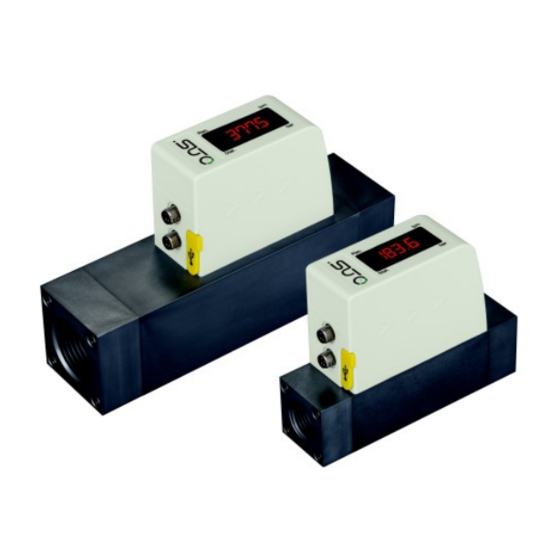
- Page 1 English Instruction and operation manual S418-V Vacuum Flow Meter (With Data Logger)
- Page 2 The device is designed exclusively for the described application. SUTO offers no guarantee for the suitability for any other purpose. SUTO is also not liable for consequential damage resulting from the delivery, capability or use of this device.
-
Page 3: Table Of Contents
11.1 Features................19 11.2 Operations................20 11.2.1 Logger configuration.............20 11.2.2 Data read-out and analysis..........20 12 Calibration................22 13 Disposal or waste..............22 14 Appendix A - Specifications............23 14.1 Vacuum flow ranges............23 14.2 Order table...............23 14.3 Error codes...............24 15 Appendix B - Modbus communication example......25 S418-V... -
Page 4: Safety Instructions
• Consider all regulations for electrical installations. • The system must be disconnected from any power supply during maintenance. • Any electrical work on system is only allowed by authorized qualified personal. S418-V... - Page 5 • Do not exceed the maximum operation temperature at the sensors tip. • Avoid condensation on the sensor element as this will affect accuracy enormously. Storage and transportation • Make sure that the transportation temperature is between -30 ... +70°C. S418-V...
-
Page 6: Registered Trademarks
• Avoid direct UV and solar radiation during storage. • For the storage the humidity must be <90%, no condensation. 2 Registered trademarks SUTO ® Registered trademark of SUTO iTEC MODBUS ® Registered trademark of the Modbus Organization, Hopkinton, USA HART ®... -
Page 7: Rf Exposure Information And Statement
• Consult the dealer or an experienced radio/TV technician for help • This device and its antenna(s) must not be co-located or operating in conjunction with any other antenna or transmitter. S418-V... -
Page 8: Application
4 Application 4 Application The S418-V is a thermal mass flow sensor that is designed to measure the actual flow at the low pressure side of vacuum pumps within the permissible operating parameters (in chapter 6 Technical data). The S418-V can measure the following values: Absolute volumetric flow (default unit: al/min) •... -
Page 9: Technical Data
6 Technical data 6 Technical data 6.1 General data FCC ID: 2ASK2-SUTO-003 Parameters Flow: Actual volumetric flow: l/min, m /min, cfm Consumption: m , ft Medium pressure: bar, psi Principle of measurement Thermal mass flow Sensor Glass coated resistive sensor... -
Page 10: Data Logger
Through mobile app S4C-FS (Free for download on Google Play Store and SUTO Website) Logger readout Through the software S4A via USB (Downloadable on the SUTO website) 6.4 Output signals Analogue output Signal: 4 ... 20 mA, isolated Scaling: 0 to max flow... -
Page 11: Accuracy Of Pressure
Pressure: bar (default) or psi Sensor Piezzo-resistive sensor Measuring range 0.01 … 1.60 bar(a) 7 Dimensional drawing A (mm) B (mm) C (mm) D (mm) E (mm) DN 8/15 35.0 48.0 120.4 35.0 93.0 DN 20/25 48.0 61.0 178.0 48.0 106.0 S418-V... -
Page 12: Installation
• The sensor is for indoor use only! At an outdoor installation, the meter must be protected from solar radiation and rain. • It is strongly recommend not to install S418-V permanently in wet environment. 8.2 LED indicators... -
Page 13: Electrical Connection
5 m cable with a M8 connector on one side and open wires on the other side. To make the S418-V work, one cable connection is sufficient. However, if the pulse output is to be used or the supply and the signal need to be on separate cables, a second connection cable must be ordered. - Page 14 Pin 1 Pin 2 Pin 3 Pin 4 Modbus Pulse and analog M-Bus M-Bus M-Bus M-Bus M-Bus Wire color brown white blue black ATTENTION! Do not screw the M8 plug using force. Otherwise, it may damage the connecting pins. S418-V...
-
Page 15: Sensor Signal Outputs
The sensor outputs one pulse per consumption unit. This pulse output can be connected to an external pulse counter to count the total consumption. The number of m per second are summed up and indicated after one second. Pulse length depends on flow rate. S418-V... - Page 16 9 Sensor signal outputs Volumetric flow Volumetric flow Pulse length Max. pulse [ms] output per hour ≦ ≦ 10800 1080 > 3 > 10800 2880 > 6 > 21600 3960 Pulse connection diagram Variant 1: Variant 2: S418-V...
-
Page 17: Modbus Output
Byte order Byte sequencing (HEX) Example MID-LITTLE-ENDIAN A B C D 0x 0A 11 42 C5 (Read from the device) LITTLE-ENDIAN B A D C 0x 11 0A C5 42 BIG-ENDIAN C D A B 0x 42 C5 0A 11 S418-V... -
Page 18: Configuration
10 Configuration 10 Configuration To change any settings on the S418-V, please download and install the service App S4C-FS from the Google Play store or our Website. This App works on any Android system with Bluetooth supported. To be allowed to change settings, the App needs to scan the QR code on the calibration certificate. -
Page 19: Read And Analysis Of Measurement Data
• The S418-V log file supports up to 5.6 million records due to its memory size, which is equivalent to 64-day data at the one- second sampling rate. -
Page 20: Operations
11.2 Operations 11.2.1 Logger configuration You can control and configure the S418-V data logger using the S4C-FS App. Detailed steps are as follows. 1. Install and launch the S4C-FS App. For more information, see the S4C-FS Instruction and Operation Manual. - Page 21 6. Click the File menu to have graphic views on measurement data in a log file; and if needed, to export this log file to the Excel or CSV format. For more information about operations on S4A, click the Help button on the top right corner. S418-V...
-
Page 22: Calibration
The sensor, the accessories and its packings must be disposed according to your local statutory requirements. The dispose can also be carried by the manufacturer of the product, for this please contact the manufacturer. S418-V... -
Page 23: Appendix A - Specifications
1000 1750 1333 2333 1000 2000 3500 2000 4000 7000 Stated measuring ranges under the following conditions: • Air at +20°C 14.2 Order table Order no. Code Description S695 419 S418-V S418-V, thermal mass flow sensor, 1.5% o.RDG., 24 S418-V... -
Page 24: Error Codes
With imperial units instead of SI units Accessories Order no. Description A554 3315 T-BOX for S418-V Modbus/M-Bus systems, including 2 m cable with a M8 connector A554 0109 Main power supply 100-240 VAC / 24 VDC, 0.5 A, 2 m cable with M8 connector... -
Page 25: Appendix B - Modbus Communication Example
Coil address Hi 1 byte Coil address Hi 1 byte Coil address Lo 1 byte Coil address Lo 1 byte Data Hi 1 byte Data Hi 1 byte Data Lo 1 byte Data L 1 byte 2 bytes 2 bytes S418-V... - Page 26 1 byte Slave address 1 byte Function code 1 byte Function code 1 byte 2 bytes Byte count 1 byte Slave ID 2 bytes Device run 2 bytes indicator Product code 2 bytes Product name 20 bytes 2 bytes S418-V...
- Page 27 S418-V...
- Page 28 SUTO iTEC GmbH SUTO iTEC (ASIA) Co., Ltd. Grißheimer Weg 21 Room 10, 6/F, Block B, Cambridge Plaza D-79423 Heitersheim 188 San Wan Road, Sheung Shui, N.T. Germany Hong Kong Tel: +49 (0) 7634 50488 00 Tel: +852 2328 9782...
Need help?
Do you have a question about the S418-V and is the answer not in the manual?
Questions and answers