Table of Contents
Advertisement
Quick Links
Advertisement
Table of Contents

Related Manuals for VOLTCRAFT DSO-2202H + AFG


Summary of Contents for VOLTCRAFT DSO-2202H + AFG
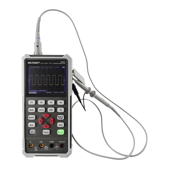
- Page 1 Handheld Oscilloscope Quick Guide DSO-2072H DSO-2202H + AFG...
-
Page 2: Table Of Contents
Tab le o f C o n te n ts 1 . S a fe ty In fo rm a tio n ......................1 2 . H o w to Im p le m en t th e G e n e ral In s p e ctio n ............4 3 . -
Page 3: S A Fe Ty In Fo Rm A Tio N
1 . S a fe ty In fo rm a tio n (Before using this product, please read the safety information in advance) S a fe ty Term s T e rm s in th is m a n u a l (The following terms may appear in this manual): W arn in g : Warning indicates conditions or practices that could result in injury or loss of life. - Page 4 To prevent electric shock or fire, use a suitable power adapter. Refer to section "General Technical Specifications" for further information relating to the power supply. Warning: The two channels of the oscilloscope are non-isolated channels. Note that the channel should use a common reference when measuring, and the ground wires of the two probes cannot be connected to two non-isolated places with different DC electrical levels, otherwise it may cause a short circuit due to the ground wire connection of the oscilloscope probe.
- Page 5 Only voltage probes and test wires with proper insulation attached to the oscilloscope or accessories suitable for oscilloscope instrument products specified by our company shall be used. Before use, check the multimeter test probe, oscilloscope probe and accessories for mechanical damage. If damage available, replace it. ...
-
Page 6: H O W To Im P Le M En T Th E G E N E Ral In S P E Ctio N
Avo id e x p o s ed c irc u it. Be careful when working on exposed circuitry to avoid risk of electric shock or other injury. D o n o t o p e ra te if a n y d a m a g e. If you suspect damage to the instrument, have it inspected by qualified service personnel before further use. -
Page 7: H O W To U S E Th E O S Cillo Sc O P E
3 . H o w to U s e th e O s c illo s c o p e O s c illo s c o p e P o w er th e The device can be powered three ways: 1) Input: USB-Cᵀᴹ... - Page 8 Figure 3- 1: Front Panel of the Oscilloscope Description: 1. CH1 and CH2 input connectors. 2. Waveform generator output connector (optional). 3. Display area. 4. The F 1 - F 4 keys are multi-function keys. In each menu mode, press the corresponding key to select the corresponding menu item.
-
Page 9: Side Panel
14. Enter the save settings key. 15. Enter the system settings key. 16. Switch key for working state of oscilloscope and multimeter. 17. CH1 / CH2 - channel switch key. Side Panel Description: 1. Probe compensation: 3.3V/1kHz square wave signal output 2. -
Page 10: Introduction To The User Interface Of The Oscilloscope
In tro d u c tio n to th e U s e r In te rfa ce o f th e O s c illo s co p e Figure 3- 2: Oscilloscope Interface Description: 1. The trigger status indicates the following information: Auto: Automatic mode. -
Page 11: Functional Check
8. Battery power and external power supply indication. 9. Channel 1 waveform. 10. The pointer indicates the trigger electrical level position of the channel. 11. Channel 2 waveform. 12. The icon indicates trigger-related information, including trigger channel, coupling mode, trigger type and trigger electrical level. 13. -
Page 12: Probe Compensation
2 . T h e s w itc h o n th e o s c illo s co p e p ro b e is s e t to 1 0X a n d c o n n e c te d w ith th e C H 1 c h a n n e l. -
Page 13: Probe Attenuation Coefficient Setting
and connect the reference wire clamp to the ground wire connector of the probe compensator, and then press the A u to key on the front panel. 2. Check the displayed waveform and adjust the probe until the compensation is correct. See F ig u re 3 - 4 and F ig u re 3 - 5 . O ve rc o m p en s a tio n C o rre c t c o m p e n sa tio n U n d e r-c o m p e n s atio n... -
Page 14: Safe Use Of Probe
N o te : The preset setting of the probe attenuation coefficient in the menu when the oscilloscope is delivered is 10X. Make sure that the attenuation switch setting value on the probe is the same as the probe attenuation coefficient option in the oscilloscope menu. -
Page 15: H O W To U S E Th E M U Ltim E Te
W arn in g : To prevent electric shock when using the probe, please keep your fingers behind the safety ring on the probe body. To prevent electric shock when using the probe, do not touch the metal part of the probe head when the probe is connected to a voltage source. - Page 16 Description: 1. Measurement type indication: D C V ------ DC voltage measurement ~ A C V ------ AC voltage measurement D C A ------ DC current measurement ~ A C A ------ AC current measurement R e s ist ------ Resistance measurement D io d e ------...
-
Page 17: H O W To U S E Th E W Ave Fo Rm G E N Era To R (O P Tio N A
5 . H o w to U s e th e W ave fo rm G e n e ra to r (o p tio n a l) The instrument can provide 4 basic waveforms, sine wave, square wave, ramp wave, pulse wave, and 8 arbitrary waveforms. C o n n e c t th e o u tp u t Press the M o d e button to switch the instrument interface to the waveform generator function interface. -
Page 18: Tro U B Les H O O Tin
6 . Tro u b le s h o o tin g 1 . T h e o s c illo s co p e c an n o t b e tu rn e d o n . It may be that the battery is completely exhausted. At this time, even if the oscilloscope is powered by the power adapter, the oscilloscope cannot be turned on. -
Page 19: A P P E N D
R U N /S T O P . Check whether the trigger mode of the trigger mode menu is normal or single, and the trigger electrical level is out of the waveform range. If so, center the trigger electrical level or set the trigger mode to automatic. In addition, you can press A u to to automatically complete the above settings. - Page 20 prevent damage to the instrument or probe. C le an in g : Check the instrument and probe frequently according to the operation. Clean the external surface of the instrument as follows: 1. Please wipe the floating dust outside the instrument and probe with a soft cloth.
- Page 21 symbol indicates the power-on charging status; symbol indicates battery power supply; symbol indicates that there is only about five minutes of use time left. Please charge as soon as possible according to the relevant tips to avoid damage to the battery. C h a rg in g M e th o d Charging the battery through the power adapter: Connect the oscilloscope to the power socket through the USB data cable and power adapter.
-
Page 22: Appendix C: Fuse Replacement
2) Replace the rechargeable batteries. Observe the polarity markings shown inside the battery compartment. 3) Replace the battery compartment cover. A p p e n d ix C : F u s e R e p la c e m e n t W arn in g : Only use fuses of the correct type and rating.
Need help?
Do you have a question about the DSO-2202H + AFG and is the answer not in the manual?
Questions and answers