Table of Contents
Advertisement
Quick Links
Advertisement
Table of Contents

Related Manuals for VOLTCRAFT DSO-111


Summary of Contents for VOLTCRAFT DSO-111
- Page 1 DSO-111 Oscilloscope Quick Guide...
-
Page 2: Table Of Contents
Table of Contents 1. General Safety Requirements.................. 1 2. Safety Terms and Symbols..................2 3. User Guidebook......................4 Structure of the Oscilloscope....................4 Front Panel...............................4 Rear Panel............................... 6 General Inspection........................7 Basic Operation......................... 7 Probe Compensation........................8 Set the Probe Attenuation Coefficient................. 9 Use the Probe Safely........................ -
Page 3: General Safety Requirements
1.General Safety Requirements 1. General Safety Requirements Before use, please read the following safety precautions to avoid any possible bodily injury and to prevent this product or any other connected products from damage. To avoid any contingent danger, ensure this product is only used within the range specified. -
Page 4: Safety Terms And Symbols
2.Safety Terms and Symbols 2. Safety Terms and Symbols Safety Terms Terms in this manual. The following terms may appear in this manual: Warning: Warning indicates the conditions or practices that could result in injury or loss of life. Caution: Caution indicates the conditions or practices that could result in damage to this product or other property. - Page 5 2.Safety Terms and Symbols To avoid body damage and prevent product and connected equipment damage, carefully read the following safety information before using the test tool. This product can only be used in the specified applications. Warning In X-Y mode, the X Input and Y Input of the oscilloscope are not electrically isolated.
-
Page 6: User Guidebook
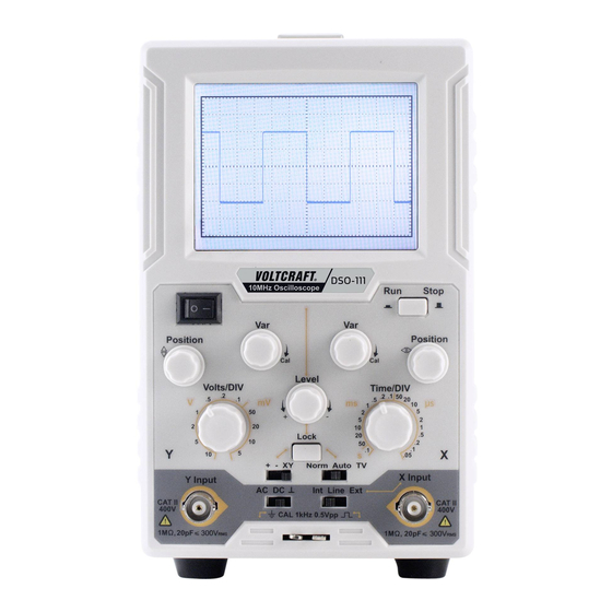
3.User Guidebook 3. User Guidebook Structure of the Oscilloscope This chapter makes a simple description of the operation and function of the front panel of the oscilloscope, enabling you to be familiar with the use of the oscilloscope in the shortest time. Front Panel Figure 3- 1 Front panel Name... - Page 7 3.User Guidebook Control signal trigger to sweep at certain level. Towards "-": The triggering level moves downward on the display waveform. Level Towards "+": The triggering level moves upward on the display waveform. Time/DIV Select the sweep rate. When the Lock button is pressed down, the triggering level is automatically maintained at Lock optimum value irrespective of the signal amplitude,...
-
Page 8: Rear Panel
3.User Guidebook +: Trigger on rising slope. Triggering occurs when the triggering signal crosses the triggering level in positive-going direction. -: Trigger on falling slope. Triggering occurs when +/-/XY the triggering signal crosses the triggering level in negative-going direction. XY: This position is used when using the instrument as an X-Y oscilloscope. -
Page 9: General Inspection
3.User Guidebook Name Description AC Power input Connect the supplied AC power cord to this connector connector. Fuse holder Fuse rating is 1A, T class, 250 V. General Inspection After you get a new oscilloscope, it is recommended that you should make a check on the instrument according to the following steps: 1. -
Page 10: Probe Compensation
3.User Guidebook Int/Line/Ext AC/DC/ Lock Pressed down 2. Connect the power cord to the AC line outlet. Press the power switch ○ — the front panel to power on, the screen will light up. A few seconds later, a trace will appear on the screen. -
Page 11: Set The Probe Attenuation Coefficient
3.User Guidebook Compensated correctly Overcompensated Under compensated Figure 3- 3 Displayed Waveforms of the Probe Compensation Figure 3- 4 Adjust Probe Set the Probe Attenuation Coefficient The probe has several attenuation coefficients, which will influence the vertical scale factor of the oscilloscope. The set values of the probe switch are 1X and 10X (see Figure 3- 5). -
Page 12: X-Y Mode
3.User Guidebook Figure 3- 6 Finger Guard Warning: To avoid electric shock, always keep your finger behind the safety guard ring of the probe during the operation. To protect you from suffering from the electric shock, do not touch any metal part of the probe tip when it is connected to the power supply. - Page 13 3.User Guidebook The signal must be centered and kept in the horizontal direction. Figure 3- 7 Lissajous Graph Based on the expression sin (q) =A/B or C/D, thereinto, q is the phase difference angle, and the definitions of A, B, C, and D are shown as the graph above.
-
Page 14: Troubleshooting
4.Troubleshooting 4. Troubleshooting 1. Oscilloscope is powered on but no display. Check whether the power connection is connected properly. Check whether the fuse which is beside the AC power input jack is blew (the cover can be pried open with a straight screwdriver). ... -
Page 15: Appendix
5.Appendix 5. Appendix Appendix A: Enclosure (The accessories subject to final delivery.) Standard Accessories: Power cord x 1 Quick guide EN x 1 Quick guide DE x 1 Safety Hintsheet x 1 Probe x 1 Probe adjust x 1 Fuse x 1 Appendix B: General Care and Cleaning General Care Do not store or leave the instrument where the display will be exposed to direct...
Need help?
Do you have a question about the DSO-111 and is the answer not in the manual?
Questions and answers