
Related Manuals for VOLTCRAFT DSO 4000


Summary of Contents for VOLTCRAFT DSO 4000
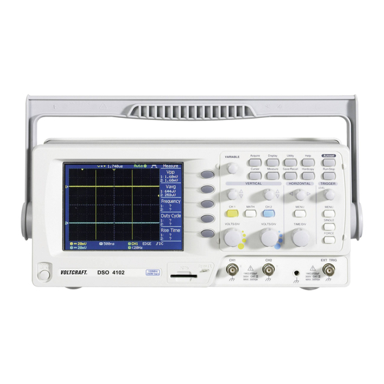
- Page 1 Digital Storage Oscilloscope DSO 4022 / 4042 / 4062 / 4102 Bestell Nr. 122460/122461/122462/122463...
-
Page 2: Table Of Contents
TABLE OF CONTENTS Table of Contents SAFETY INSTRUCTION ......... 6 Safety Symbols ..............6 Safety Guidelines..............7 Power cord for the United Kingdom ........9 GETTING STARTED........10 Main Features ..............10 Panel Overview ............... 11 Front Panel................11 Rear Panel.................14 Display................15 Setting up the Oscilloscope ..........16 QUICK REFERENCE ........ - Page 3 TABLE OF CONTENTS TABLE OF CONTENTS Trigger key 2/4..............29 Zooming the waveform horizontally ........56 Trigger key 3/4..............29 Viewing waveforms in the X-Y mode........57 Trigger key 4/4..............30 Vertical View (Channel) ........... 58 Utility key 1/4..............30 Moving the waveform position vertically......58 Utility key 2/4..............
-
Page 4: Safety Instruction
TABLE OF CONTENTS DSO-4000 User Manual MAINTENANCE .......... 90 Vertical Resolution Calibration......... 90 Probe Compensation ............91 AFETY INSTRUCTION FAQ ............93 The input signal does not appear in the display....93 I want to remove some contents from the display..... 93 This chapter contains important safety instructions The waveform does not update (frozen)...... -
Page 5: Safety Guidelines
DSO-4000 User Manual Fuse Fuse type: T1A/250V • Safety Guidelines To ensure fire protection, replace the fuse only • WARNING with the specified type and rating. General Make sure the BNC input voltage does not • Disconnect the power cord before replacing the •... -
Page 6: Power Cord For The United Kingdom
DSO-4000 User Manual Storage Location: Indoor • environment Relative Humidity: < 85% • Temperature: 0°C to 50°C • ETTING STARTED Power cord for the United Kingdom When using the oscilloscope in the United Kingdom, make sure the The Getting started chapter introduces the power cord meets the following safety instructions. -
Page 7: Panel Overview
DSO-4000 User Manual Panel Overview Configures the Hardcopy function Utility key Utility (page76), shows the system status (page68), selects the menu Front Panel language (page70), runs the self calibration (page90), and configures the probe compensation signal(page91). Help key Shows the Help contents on the Help display (page33). -
Page 8: Rear Panel
DSO-4000 User Manual Horizontal Moves the waveform horizontally position knob (page54). Rear Panel TIME/DIV knob Selects the horizontal scale TIME/DIV (page54). Vertical position Moves the waveform vertically knob (page58). CH1/CH2 key Configures the vertical scale and CH 1 coupling mode for each channel (page58). -
Page 9: Display
DSO-4000 User Manual Display Setting up the Oscilloscope Waveform marker Waveform position Trigger status Acquisition Background This section describes how to set up the oscilloscope properly including connecting a signal, adjusting the scale, and compensating the probe. Before operating the oscilloscope in a new Menu environment, run these steps to make sure the oscilloscope is functionally stable. -
Page 10: Quick Reference
DSO-4000 User Manual 6. Press the Autoset key. A Autoset square waveform will appear in the center of the display. For details of the UICK REFERENCE Autoset, see page35. 7. Press the Display key, then This chapter lists the oscilloscope menu tree, Type and select the vector operation shortcuts, built-in help coverage, and waveform. -
Page 11: Autoset Key
DSO-4000 User Manual Autoset key Cursor key 2/2 Automatically find signal Autoset Autoset and set scale Turn cursor on/off Cursor CH1/2 key Move Y1 cursor Turn channel on/off Move Y2 cursor CH 1/2 Select coupling mode Move both Y1 and Y2 cursor Coupling Y1Y2 Invert waveform... -
Page 12: Hardcopy Key
DSO-4000 User Manual Hardcopy key Math key 1/2 See Utility key (page30) Math on/off Math Select math operation type (+/–) Help key Operation Select addition/subtraction Turn help mode on/off CH1+/-CH2 Help Set result position Position VAR Horizontal menu key Math result Volt/Div Select main (default) display Unit/Div VAR Main... -
Page 13: Measure Key
DSO-4000 User Manual Measure key Save/Recall key 1/9 Switch to Save or Recall menu Save/Recall Turn on/off measurement Measure Recall default setup Default Setup Select measurement type Voltage/Time Save/Recall key 2/9 Select measurement item or Icon Go back to previous menu Previous Menu Select other menu Recall Setup... -
Page 14: Save/Recall Key 3/9
DSO-4000 User Manual Save/Recall key 3/9 Save/Recall key 5/9 Select other menu Select other menu Save Setup Save Recall Waveform Save Setup Setup Select waveform source Select destination Source Destination Destination Select waveform destination Save setup Memory/SD Card Memory Save Destination VAR Save Go to SD card file utilities... -
Page 15: Save/Recall Key 7/9
DSO-4000 User Manual Save/Recall key 7/9 Save/Recall key 9/9 Select other menu Select file/folder Select Save Image Turn on/off ink saver Create or rename folder/file New Folder/Rename Ink Saver Enter character / Save image Backspace / Save / Previous menu Save Delete folder/file Go to SD card file utilities... -
Page 16: Trigger Key 2/4
DSO-4000 User Manual Trigger key 2/4 Trigger key 4/4 Select edge trigger type Select trigger slope type Edge Trigger MENU Edge Slope Select trigger source Select trigger coupling mode Type Source Coupling Edge Go to slope/coupling menu Select frequency rejection Source CH1/2/Ext/Line (page30) -
Page 17: Utility Key 1/4
DSO-4000 User Manual Default Settings Utility key 2/4 Here are the factory installed panel settings which Enter self calibration appear when pressing the Save/Recall key Self CAL Default Setup. Go to previous menu Acquisition Mode: Normal Previous Menu Channel Scale: 2V/Div Invert: Off Coupling: DC Probe attenuation: x1... -
Page 18: Built-In Help
DSO-4000 User Manual Built-in Help The Help key shows the contents of the built-in Help EASUREMENT help support. When you press a function key, its descriptions appear in the display. Applicable keys Acquire Display Utility Help Autoset The Measurement chapter describes how to properly observe a signal using the oscilloscope’s Cursor Measure... -
Page 19: Using The Autoset
DSO-4000 User Manual Undoing the To undo the Autoset, press De-activating a To de-activate the channel, press the Channel key Autoset Undo (available for 5 seconds). channel twice (once if the channel menu is already selected). Adjusting the If the waveform is still LEVE L trigger level unstable, try adjusting the... -
Page 20: Changing The Horizontal Position And Scale
DSO-4000 User Manual To select the timebase (scale), turn Selecting the TIME/DIV horizontal scale the TIME/DIV knob; left (slow) or right (fast). Range 1ns/Div ~ 10s/Div, 1-2-5 increment Waveforms can be moved or scaled in both the Waveform operation Run and Stop mode. For details, see page54 (Horizontal position/scale) and page58 (Vertical position/scale). -
Page 21: Using The Probe Compensation Signal
DSO-4000 User Manual Using the probe compensation signal 3. Press ProbeComp. Background This section introduces how to use the probe compensation signal for general usage, in case the DUT 4. Press Wave type repeatedly signal is not available or to get a to select the wave type. -
Page 22: Automatic Measurements
DSO-4000 User Manual Automatic Measurements Vavg Averaged voltage of the first cycle. Automatic measurement function measures input signal attributes and updates them in the display. Vrms RMS (root mean square) voltage. Measurement items ROVShoot Rise overshoot voltage. Overview Voltage type Time type FOVShoot Fall overshoot voltage. -
Page 23: Automatically Measuring The Input Signals
DSO-4000 User Manual Cursor Measurements Automatically measuring the input signals Cursor line, horizontal or vertical, shows the precise position of the input waveforms or math operation result. Viewing the 1. Press the Measure key. Measure measurement result Using the horizontal cursors 2. -
Page 24: Using The Vertical Cursors
DSO-4000 User Manual Math Operations Using the vertical cursors The Math operations can add, subtract, or perform FFT on the input waveforms. The resulted waveform can be measured using the Procedure 1. Press the Cursor key. Cursor cursors, and saved or recalled just like normal input signals. 2. -
Page 25: Adding Or Subtracting Signals
DSO-4000 User Manual Adding or subtracting signals Using the FFT function Procedure 1. Activate both CH1 and CH 1 CH 2 Procedure 1. Press the Math key. CH2. 2. Press Operation repeatedly 2. Press the Math key. to select FFT. 3. -
Page 26: Configuration
DSO-4000 User Manual Average Multiple data are averaged to form a waveform. This mode is useful for drawing a noise-free waveform. To ONFIGURATION select the number, press Average repeatedly. Average number: 2, 4, 8, 16, 32, 64, 128, The Configuration chapter describes how to configure panel settings to make measurements Peak detect To activate the Peak detect mode, and observations suited to the application needs. -
Page 27: Real Time Vs Equivalent Time Sampling Mode
DSO-4000 User Manual 6. Press the Acquire key. Display Acquire The Display section describes how to configure the display settings: drawing type, waveform accumulation, contrast adjustment, and 7. Press Normal. grid settings. 8. Press Peak-Detect and see Selecting the vector or dot drawing Peak that a spike noise is Detect... -
Page 28: Adjusting The Display Contrast
DSO-4000 User Manual Horizontal View Example Accumulation off Accumulation on The Horizontal view section describes how to configure the horizontal scale, position, waveform update mode, window zoom, and X-Y mode. Moving the waveform position horizontally Procedure The horizontal position knob moves the waveform left or Adjusting the display contrast right. -
Page 29: Selecting The Waveform Update Mode
DSO-4000 User Manual Selecting the waveform update mode Zooming the waveform horizontally Background The display update mode is switched Procedure/ range 1. Press the Horizontal Menu MENU automatically or manually according to the key. horizontal scale. Updates the whole displayed waveform at once. Main mode 2. -
Page 30: Viewing Waveforms In The X-Y Mode
DSO-4000 User Manual Viewing waveforms in the X-Y mode Vertical View (Channel) The X-Y mode compares the voltage of Channel 1 Background The Vertical view section describes how to set the vertical scale, and Channel 2 waveforms in a single display. This position, bandwidth limitation, coupling mode, and attenuation. -
Page 31: Inverting The Waveform Vertically
DSO-4000 User Manual AC coupling mode. Only the AC portion of the signal appears on the 2. Press BW Limit to turn on or display. This mode is useful for observing AC waveforms mixed with off the limitation. When turned on, the BW incicator DC signal. -
Page 32: Trigger
DSO-4000 User Manual Trigger The Auto trigger status appears in the upper right corner of the display. The Trigger function configures the conditions by which the oscilloscope captures the incoming signals. Trigger type Single The oscilloscope acquires the SINGLE Edge Triggers when the signal crosses an amplitude input signals once when a threshold in either positive or negative slope. -
Page 33: Configuring The Edge Trigger
DSO-4000 User Manual Pulse condition Sets the pulse width (20ns ~ 200us) and the (pulse trigger) triggering condition. 4. Press Mode repeatedly to > Longer than Equal to select the Auto or Normal < Shorter than Not equal to trigger mode. To select the Single trigger mode, press Trigger slope Triggers on the rising edge. -
Page 34: Configuring The Video Trigger
DSO-4000 User Manual Configuring the video trigger Configuring the pulse width trigger Procedure 1. Press the Trigger menu key. MENU Procedure 1. Press the Trigger menu key. MENU 2. Press Type repeatedly to select video trigger. The 2. Press Type repeatedly to video trigger indicator select pulse width trigger. -
Page 35: Manually Triggering The Signal
DSO-4000 User Manual 7. Press Slope repeatedly to Manually triggering the signal select the trigger slope, which also appears at the Note This section describes how to manually trigger the bottom of the display. input signals when the oscilloscope does not Rising edge, falling edge Range capture them. -
Page 36: Remote Control Interface
DSO-4000 User Manual Remote Control Interface System Settings The Remote control interface section describes how to set up the The system settings show the oscilloscope’s system information and USB interface for PC connection. The details of remote control allow changing the language. commands are described in the DSO-4000 Programming Manual. - Page 37 DSO-4000 User Manual External SD An SD card (2GB or less, FAT or card FAT32 format) can hold practically AVE/RECALL unlimited number of waveforms. Ref A, B The two reference waveforms are used as the buffer to recall a waveform in the display.
- Page 38 DSO-4000 User Manual Using the SD card file utilities Setup file format For the SD card inserted into the oscilloscope, file Background Format xxxx.set (proprietary format) deletion, folder creation, file/folder rename are A setup file saves or recalls the following settings. available from the front panel.
-
Page 39: Quick Save (Hardcopy)
DSO-4000 User Manual 1. Move the cursor to the file Quick Save (HardCopy) Creating a new folder / renaming or folder location and press a file or folder New Folder or Rename. The Background The Hardcopy key works as a Hardcopy file/folder name and the shortcut for saving display... -
Page 40: Save
DSO-4000 User Manual 5. To invert the color in the Save display image, press Ink This section describes how to save data using the Save/Recall menu. Saver and turn on or off the Ink Saver. File type/source/destination 6. Press the Hardcopy key. Hardcopy The file or folder will be Item... -
Page 41: Saving The Panel Settings
DSO-4000 User Manual Saving the panel settings Saving the waveform Procedure 1. (For saving to an external SD card) Insert the card into Procedure 1. (For saving to an external the slot. SD card) Insert the card into 2. Press the Save/Recall key Save/Recall Save/Recall the slot. -
Page 42: Saving The Display Image
DSO-4000 User Manual 6. Press Save to confirm SD card External card, no practical saving. When completed, a limitation on the amount of file. message appears at the When saved, the image file will be bottom of the display. placed in the root directory. The file will not be saved if the Note power is turned off or the SD card is... -
Page 43: Recall
DSO-4000 User Manual Waveform data Two types of waveform data Recall (Axxxx.csv) are saved: the currently active channel data and the last File type/source/destination internally saved data (one of W1 ~ W15). Item Source Destination Default panel Factory installed Current front panel 4. -
Page 44: Recalling A Reference Waveform To The Display
DSO-4000 User Manual Recalling a reference waveform to the display Cursor Source: CH1 Horizontal: None Vertical: None Procedure 1. The reference waveform must be stored in Display Type: Vectors Accumulate: Off advance. See page80 for details. Graticule: 2. Press the Save/Recall key. Save/Recall Horizontal Scale: 2.5us/Div... -
Page 45: Recalling Panel Settings
DSO-4000 User Manual Recalling panel settings Recalling a waveform 1. (For recalling from an Procedure external SD card) Insert the Procedure 1. (For recalling from an card into the slot. external SD card) Insert the card into the slot. 2. Press the Save/Recall key. Save/Recall 2. -
Page 46: Vertical Resolution Calibration
DSO-4000 User Manual 6. Press Recall to confirm recalling. When completed, a message appears at the bottom of the display. AINTENANCE The file will not be saved if the Note power is turned off or SD card is disconnected before completion. Two types of maintenance operations are available: calibrating the vertical resolution, and To edit SD card contents... -
Page 47: Probe Compensation
DSO-4000 User Manual 7. The Channel1 calibration 5. Press the Autoset key. The Autoset Ch1 calibration 1/3 will complete in less than 5 compensation signal will minutes. appear in the display. 6. Press the Display key, then 8. When finished, connect the Type to select the vector Done!! calibration signal to the... -
Page 48: Faq
DSO-4000 User Manual The probe waveform is distorted. You might need to compensate the probe. For details, see page91. Note that the frequency accuracy and duty factor are not specified for probe compensation waveform and therefore it should not be used for other reference purpose. -
Page 49: Appendix
DSO-4000 User Manual DSO-4000 Series Specifications The specifications apply when the oscilloscope is powered on for at least 30 minutes under +20°C~+30°C. PPENDIX Model-specific specifications Fuse Replacement DSO-4022 Bandwidth ( 3dB) DC coupling: DC ~ 25MHz AC coupling: 10Hz ~ 25MHz Bandwidth Limit None Trigger Sensitivity Approx. -
Page 50: Common Specifications
DSO-4000 User Manual Cursors and Voltage Vpp, Vamp, Vavg, Vrms, Vhi, Vlo, Vmax, Common specifications Measurement Vmin, Rise Preshoot/ Overshoot, Fall Preshoot/ Overshoot Vertical Sensitivity 2mV/div~5V/Div (1-2-5 increments) Time Freq, Period, Rise Time, Fall Time, + Accuracy ± (3% x |Readout|+0.1div + 1mV) Width, –... -
Page 51: Probe Specifications
DSO-4000 User Manual Probe Specifications Declaration of Conformity The below mentioned products DSO-4022/4042 Probe Type of Product: Digital Storage Oscilloscope Model Number: DSO-4022, DSO-4042, DSO-4062, DSO-4102 Applicable model & DSO-4022, DSO-4042 are herewith confirmed to comply with the requirements set out in probe GTP-060A-4 the Council Directive on the Approximation of the Law of Member... -
Page 52: Index
DSO-4000 User Manual frequency rejection....63 peak detect acquisition .....50 peak to peak measure ....41 front panel diagram ....11 fuse replacement .......95 peak voltage measure ....41 safety instruction ......8 power on/off general purpose signal....39 safety instruction......7 NDEX ground switch overview ......14 preshoot voltage measure..42 coupling ........... - Page 53 faq ............94 status indicator....... 15 file menu tree ........28 video ..........65 file operation ........74 UK power cord......9 SECAM........62 USB for remote control.....69 serial number ......70 utility service operation key overview ........12 about disassembly......7 menu tree......... 30 contact..........94 shortcut ..........
Need help?
Do you have a question about the DSO 4000 and is the answer not in the manual?
Questions and answers