VOLTCRAFT DSO-2072H User Manual
Handheld oscilloscope
Hide thumbs
Also See for DSO-2072H:
- Quick manual (23 pages) ,
- Safety information manual (9 pages) ,
- User manual (41 pages)
Table of Contents
Advertisement
Quick Links
Advertisement
Table of Contents

Related Manuals for VOLTCRAFT DSO-2072H


Summary of Contents for VOLTCRAFT DSO-2072H
- Page 1 DSO-2072H Handheld Oscilloscope User Manual...
-
Page 2: Table Of Contents
Tab le o f C o n ten ts S a fe ty In fo rm a tio n ····················································································1 H o w to Im p le m en t th e G e n e ral In s p e ctio n ··········································· 4 H o w to U s e th e O s c illo s co p e ·································································... -
Page 3: S A Fe Ty In Fo Rm A Tio
1 . S a fe ty In fo rm a tio n (Before using this product, please read the safety information in advance) S a fe ty Term s T e rm s in th is m a n u a l (The following terms may appear in this manual): W arn in g : Warning indicates conditions or practices that could result in injury or loss of life. - Page 4 Warning: To prevent electric shock or fire, use a suitable power adapter. Refer to section "General Technical Specifications" for further information relating to the power supply. Warning: The two channels of the oscilloscope are non-isolated channels. Note that the channel should use a common reference when measuring, and the ground wires of the two probes cannot be connected to two non-isolated places with different DC electrical levels, otherwise it may cause a short circuit due to the ground wire connection of the oscilloscope probe.
- Page 5 Warning: If the input port of the oscilloscope is connected to a voltage with a peak value higher than 42V (30vrms) or a circuit with a peak value of more than 4800 VA, the following measures shall be taken to avoid electric shock or fire: ...
-
Page 6: 2 . H O W To Im P Le M E N T Th E G E N E Ra L In S P E C Tio N
O n ly a q u a lifie d p e rs o n s h o u ld p e rfo rm in te rn a l m a in te n a n ce . C h e c k a ll Term in a l R a tin g s . To avoid fire or shock hazard, check all ratings and markings on this product. -
Page 7: 3 . H O W To U S E Th E O S C Illo S C O P E
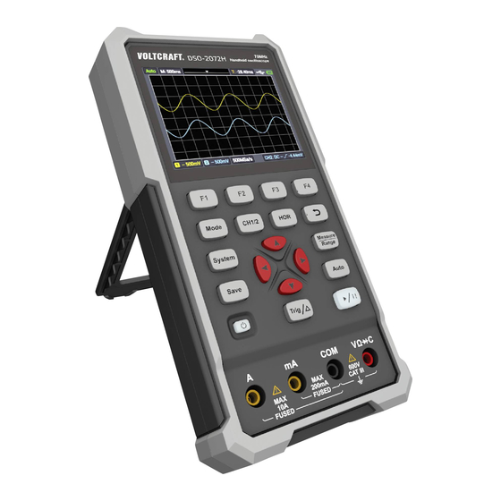
3 . H o w to U s e th e O s c illo s c o p e O s c illo s c o p e P o w er th e The device can be powered three ways: 1) Input: USB-Cᵀᴹ... - Page 8 Figure 3- 1: Front Panel of the Oscilloscope Description: 1. CH1 and CH2 input connectors. 2. Waveform generator output connector (optional). 3. Display area. 4. The F 1 - F 4 keys are multi-function keys. In each menu mode, press the corresponding key to select the corresponding menu item.
- Page 9 7. Measurement menu key (oscilloscope) or range key (multimeter). 8. Zoom or move key: Function of direction keys : used for the up and down movements of waveform, the time base changing, the voltage cursor movements and the trigger of electrical level change in the oscilloscope; Function of direction keys : used for the left and right movements of waveform, the voltage position changing and the movements of time...
-
Page 10: Side Panel
Side Panel Description: 1. Probe compensation: 3.3V/1kHz square wave signal output 2. Charging or USB communication interface 3. Bracket... -
Page 11: Introduction To The User Interface Of The Oscilloscope
In tro d u c tio n to th e U s e r In te rfa ce o f th e O s c illo s co p e Figure 3- 2: Oscilloscope Interface Description: 1. The trigger status indicates the following information: Auto: Automatic mode. -
Page 12: Functional Check
8. Battery power and external power supply indication. 9. Channel 1 waveform. 10. The pointer indicates the trigger electrical level position of the channel. 11. Channel 2 waveform. 12. The icon indicates trigger-related information, including trigger channel, coupling mode, trigger type and trigger electrical level. For details, please refer to P17 Trigger System. -
Page 13: Probe Compensation
2 . T h e s w itc h o n th e o s c illo s co p e p ro b e is s e t to 1 0X a n d c o n n e c te d w ith th e C H 1 c h a n n e l. -
Page 14: Probe Attenuation Coefficient Setting
and connect the reference wire clamp to the ground wire connector of the probe compensator, and then press the A u to key on the front panel. 2. Check the displayed waveform and adjust the probe until the compensation is correct. See F ig u re 3 - 4 and F ig u re 3 - 5 . O ve rc o m p en s a tio n C o rre c t c o m p e n sa tio n U n d e r-c o m p e n s atio n... -
Page 15: Safe Use Of Probe
N o te : The preset setting of the probe attenuation coefficient in the menu when the oscilloscope is delivered is 10X. Make sure that the attenuation switch setting value on the probe is the same as the probe attenuation coefficient option in the oscilloscope menu. -
Page 16: Vertical System
W arn in g : To prevent electric shock when using the probe, please keep your fingers behind the safety ring on the probe body. To prevent electric shock when using the probe, do not touch the metal part of the probe head when the probe is connected to a voltage source. -
Page 17: Horizontal System
Disconnect the input signal. Choose one of the values according to the probe attenuation factor to keep the vertical scale Probe 100X reading accurate. 1000X Limit the bandwidth to 20MHz to reduce display noise. Bandwidth Full bandwidth The bandwidth of the oscilloscope. H o rizo n ta l S ys te m Press the H O R key to enter the horizontal system setting menu. -
Page 18: Measuring System
M e as u rin g S ys te m A u to m atic M easu rem en t and the F 1 key to realize automatic measurement. There are 7 Press types of measurement, and up to 6 types of measurement can be displayed at the bottom left of the screen. - Page 19 When the type is selected as C H 1 or C H 2 , press the arrow keys to move the cursor line A; when the type is selected as T im e, press the arrow keys to move the cursor line a. When the type is selected as C H 1 or C H 2 , press the arrow keys to move the cursor line B;...
- Page 20 bottom right corner of the screen, e.g. . It indicates that the trigger type is rising edge, the trigger source is CH1, the trigger coupling is DC, and the trigger electrical level is -20.0mV. The description of the trigger system setting menu is as follows: F u n c tio n D e s c rip tio n S e ttin g...
- Page 21 S e ttin g s Any setting can be saved inside the oscilloscope, and restore settings can also be called. The description of S e ttin g menu is as follows: F u n c tio n D e s crip tio n S e ttin g M e n u Target...
- Page 22 F ile The file can be saved as waveform or image. The waveform and image can be read by plugging and unplugging the USB data cable or selecting MSC in the USB option on the next page of system settings. The description of F ile menu is as follows: F u n c tio n D e s c rip tio n...
- Page 23 Elapsed 00h:00m Display how long it has been powered on. runtime S ys te m The description of the menu is as follows: F u n c tio n D e s crip tio n S e ttin g M e n u Simplified Language...
-
Page 24: H O W To U S E Th E M U Ltim E Te
the built-in memory. 2) H ID [H u m a n in te rfa c e D e vic e ] is used to select the oscilloscope device as the host computer to control and communicate with the computer. F a c to ry S e ttin g s To set the factory settings, press the S ys te m key. - Page 25 Multimeter Interface Description: 1. Measurement type indication: D C V ------ DC voltage measurement ~ A C V ------ AC voltage measurement D C A ------ DC current measurement ~ A C A ------ AC current measurement R e s ist ------ Resistance measurement D io d e...
- Page 26 6. “Hold” can keep the current reading on the display. 7. Measurement value and unit. 8. Display of switching resistance, buzzer, diode and capacitance measurement function. 9. The selected range V or mV in voltage measurement; the selected current range A or mA in current measurement. 10.
-
Page 27: H O W To U S E Th E W Ave Fo Rm G E N E Rato R (O P Tio N A
5 . H o w to U s e th e W ave fo rm G e n e ra to r (o p tio n a l) The instrument can provide 4 basic waveforms, sine wave, square wave, ramp wave, pulse wave, and 8 arbitrary waveforms. C o n n e c t th e o u tp u t Press the M o d e button to switch the instrument interface to the waveform generator function interface. -
Page 28: Output The Sine Waveform
is 50Ω). N o te : To change the load value, after selecting *Ω, press direction key to move the cursor left and right; press direction key to change the value. The load range is 1 Ω - 10 kΩ. O u tp u t th e s in e w ave fo rm The sine waveform setting menu includes: Frequency/Period, Amplitude/High Level, Offset/Low Level. -
Page 29: Output The Square Waveform
O u tp u t th e s q u a re w ave fo rm Press the F 1 key to enter the square waveform setting interface. The square waveform setting menu includes: Frequency/Period, Start Phase, Amplitude/High Level, Offset/Low Level. For the setting frequency/period, amplitude/high level, offset/low level, please refer to O u tpu t th e sin e w ave form on page 26. -
Page 30: Output The Arbitrary Waveform
column. Press F 2 to switch between Rise Time / Fall Time. O u tp u t th e A rb itrary w ave fo rm Press the F 1 key to enter the arbitrary waveform setting interface. arbitrary waveform setting menu includes:... -
Page 31: C O M M U N Ic A Tio N W Ith P
6 . C o m m u n ic a tio n w ith P C The oscilloscope supports communications with a PC through USB. You can use the Oscilloscope communication software to store, analyze, display the data and remote control. To learn about how to operate the software, you can push F1 in the software to open the help document. -
Page 32: Tro U B Le Sh O O Tin
7 . Tro u b le s h o o tin g 1 . T h e o s c illo s co p e c an n o t b e tu rn e d o n . It may be that the battery is completely exhausted. At this time, even if the oscilloscope is powered by the power adapter, the oscilloscope cannot be turned on. -
Page 33: Tech N Ic A L S P E Cific Atio N
R U N /S T O P . Check whether the trigger mode of the trigger mode menu is normal or single, and the trigger electrical level is out of the waveform range. If so, center the trigger electrical level or set the trigger mode to automatic. In addition, you can press A u to to automatically complete the above settings. - Page 34 C h a ra c teris tics D e s c rip tio n Probe attenuation 1X, 10X, 100X, 1000X, 10000X Maximum input 400 V (DC + AC, PK - PK) voltage Bandwidth limit 20 MHz, Full bandwidth Sampling rate range 0.25 Sa/s~250 MSa/s Waveform (Sinx)/x...
-
Page 35: Multimeter
C h a ra c teris tics D e s c rip tio n According to Record length and time Trigger displacement base Edge trigging Slope Rising edge, falling edge T h e o u tp u t o f th e p ro b e c o m p e n s ato r: C h a ra c teris tics D e s crip tio n Output voltage... -
Page 36: Arbitrary Waveform Generator (Optional)
B a s ic M in im u m R a n g e A c c u ra c y fu n c tio n re so lu tio n Overload protection: mA function: self-healing fuse 400 mA/250 V; Ampere function: 10A/600 V, D5.2*20, fast-acting fuse 200.00mA 0.01mA... - Page 37 A m p litu d e (5 0Ω 0.01Vpp ~ 2.5Vpp D C o ffs e t (H ig h Z ) ±(2.5V – Amplitude Vpp/2) F re q u e n cy R e s o lu tio n 0.01% C h a n n e l W ave fo rm D e p th...
-
Page 38: General Technical Specifications
G e n e ral Tech n ic a l S p e c ific atio n s D is p lay: C h a ra c teris tics D e s c rip tio n Display type 3.5-inch color LCD display Display resolution 320 horizontal ×... -
Page 39: A P P E N D
9 . A p p e n d ix A p p e n d ix A : L is t o f A c c e s s o rie s Oscilloscope USB-Cᵀᴹ to USB-A (data/charging) cable ... - Page 40 2. Wipe the instrument with a damp but non-dripping soft cloth. Please disconnect the power supply. It can be scrubbed with soft detergent or water. Do not use any abrasive chemical cleaning agent to avoid damaging the instrument or probe. W arn in g : Please make sure the instrument is dry before re-energizing to avoid electrical short circuit or personal injury caused by moisture.
- Page 41 C h a rg in g M e th o d Charging the battery through the power adapter: Connect the oscilloscope to the power socket through the USB data cable and power adapter. Charge the oscilloscope through the USB interface: Connect the oscilloscope to a computer or other equipment through a USB data cable for charging (pay attention to the load capacity of the power supply equipment to avoid abnormal operation of the equipment).
-
Page 42: Appendix C: Fuse Replacement
A p p e n d ix C : F u s e R e p la c e m e n t W arn in g : Only use fuses of the correct type and rating. - Never use repaired fuses or bypass the fuse holder. a ) P re p ara tio n 1) Switch the product OFF.
Need help?
Do you have a question about the DSO-2072H and is the answer not in the manual?
Questions and answers