Table of Contents
Advertisement
Quick Links
- 1 Features of the Um-550/880
- 2 Names of Things and What They Do
- 3 Installing & Setting up the Driver (Macintosh)
- 4 The Functions of the Um-550/880
- 5 Displaying the MIDI Inputs/Outputs (MIDI Indi)
- 6 Merging Multiple MIDI Inputs for Output (Merge)
- 7 Setup Mode (P.save+Utility)
- 8 Specifications
- Download this manual
Owner's Manual
Thank you for purchasing the UM-550/880.
This document explains how to setup the UM-550/880 system. To
avoid problems and enjoy optimal performance, please carefully
follow the setup instructions described in this document.
Before using this unit, carefully read the sections entitled:
"IMPORTANT SAFETY INSTRUCTIONS" (Owner's manual p. 2),
"USING THE UNIT SAFELY" (Owner's manual pp. 3--5), and
"IMPORTANT NOTES" (Owner's manual p. 6,7). These sections
provide important information concerning the proper operation of the
unit. Additionally, in order to feel assured that you have gained a
good grasp of every feature provided by your new unit, Owner's
Manual should be read in its entirety. The manual should be saved
and kept on hand as a convenient reference.
Copyright © 2002 ROLAND CORPORATION
All rights reserved. No part of this publication may be reproduced in any form
without the written permission of ROLAND CORPORATION.
Advertisement
Table of Contents

Related Manuals for Edirol UM-550


Summary of Contents for Edirol UM-550
- Page 1 Owner’s Manual Thank you for purchasing the UM-550/880. This document explains how to setup the UM-550/880 system. To avoid problems and enjoy optimal performance, please carefully follow the setup instructions described in this document. Before using this unit, carefully read the sections entitled: “IMPORTANT SAFETY INSTRUCTIONS”...
- Page 2 CAUTION RISK OF ELECTRIC SHOCK DO NOT OPEN ATTENTION : RISQUE DE CHOC ELECTRIQUE NE PAS OUVRIR CAUTION: TO REDUCE THE RISK OF ELECTRIC SHOCK, DO NOT REMOVE COVER (OR BACK). NO USER-SERVICEABLE PARTS INSIDE. REFER SERVICING TO QUALIFIED SERVICE PERSONNEL. INSTRUCTIONS PERTAINING TO A RISK OF FIRE, ELECTRIC SHOCK, OR INJURY TO PERSONS.
-
Page 3: Using The Unit Safely
Roland. • When using the unit with a rack or stand recommended by Roland, the rack or stand must be carefully placed so it is level and sure to remain stable. If not using a rack or... - Page 4 (water, soft drinks, etc.) to penetrate the unit. 012c • Immediately turn the power off, remove the AC adaptor from the outlet, and request servicing by your retailer, the nearest Roland Service Center, or an authorized Roland distributor, as listed on the "Information" page when: •...
- Page 5 109a • Before cleaning the unit, turn off the power and unplug the power cord from the outlet. 109b • Before cleaning the unit, turn off the power and unplug the AC adaptor from the outlet. 110a • Whenever you suspect the possibility of lightning in your area, pull the plug on the power cord out of the outlet.
-
Page 6: Important Notes
• Unfortunately, it may be impossible to restore the contents of data that was stored in another MIDI device (e.g., a sequencer) once it has been lost. Roland Corporation assumes no liability concerning such loss of data. • Use a reasonable amount of care when using the unit’s buttons, sliders, or other controls;... -
Page 7: Table Of Contents
Contents USING THE UNIT SAFELY... 3 IMPORTANT NOTES ... 6 Features of the UM-550/880 ... 8 Contents of the Package ... 9 Names of Things and What They Do... 11 Installing & Setting Up the Driver (Windows)... 14 Installing & Setting Up the Driver (Macintosh)... 29 The functions of the UM-550/880... -
Page 8: Features Of The Um-550/880
The UM-550/880 is a USB MIDI interface, which uses USB for connecting to your computer. 5-in/5-out or 8-in/8-out USB MIDI interface The UM-550 has five sets of MIDI input/output ports, letting you control up to 80 channels simultaneously. Since up to four units can be used together, you can expand your system to 320 channels. -
Page 9: Contents Of The Package
AC adaptor This is included only with the UM-550. This is the only AC adaptor you should use with the UM-550. Do not use any AC adaptor other than the supplied one, since doing so may cause malfunction. Rack-mount adaptor Use this when you want to install the UM-550 in an audio rack. - Page 10 Contents of the Package USB Cable Use this to connect the USB connector of your computer with the USB connector of the UM-550/ 880. For details on connections and driver installation, refer to Windows (p. 14) or Macintosh (p. 29).
-
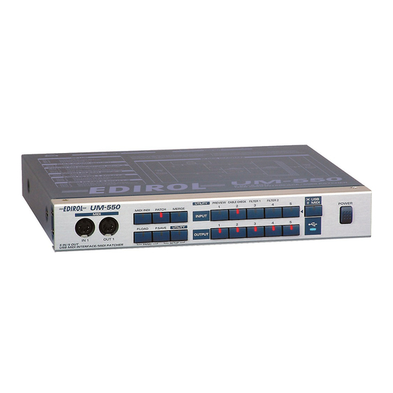
Page 11: Names Of Things And What They Do
Names of Things and What They Do Front panel UM-550 fig.550name_50 5 6 7 8 9 10 UM-880 fig.880name_50 1. USB connector (front) A USB cable connected between this connector and your computer is used to transfer MIDI messages, as well as the signals for controlling the UM-880. - Page 12 If this button is dark, the INPUT buttons correspond to inputs from the MIDI IN connectors. 14. USB indicator After a USB cable is used to connect the UM-550/880 to your computer, this indicator will light when the connection is operable.
-
Page 13: Rear Panel
When the unit is grounded, a slight hum may occur, depending on the particulars of your installation. If you are unsure of the connection method, contact the nearest EDIROL/Roland Service Center, or an authorized EDIROL/Roland distributor, as listed on the “Information” page. -
Page 14: Installing & Setting Up The Driver (Windows)
Installing & Setting Up the Driver (Windows) In order to use the UM-550/880, you must first install the UM-550/880 driver. The UM-550/880 Driver is included in the CD-ROM. The installation procedure will differ depending on your system. Please proceed to one of the following sections, depending on the system you use. - Page 15 fig.2-1 Open the Driver Signing Options dialog box. Click the Hardware tab, and then click [Driver Signing]. fig.2-2 Make sure that “What action do you want Windows to take?” is set to “Ignore.” If it is set to “Ignore”, simply click [OK].
- Page 16 550. Alternatively, connect the AC cable to the UM-880. 2. Connect the AC adaptor or the AC cable to an electrical outlet. 3. Use the USB cable to connect the UM-550 to your computer. Set the UM-550’s power switch to the ON position.
- Page 17 [Next]. fig.2-8_20 Make sure that the “Model” field indicates “EDIROL UM-550,” and click [Next]. Driver installation will begin. If the “What action do you want Windows to take?” setting was not set to “Ignore”, a “Hardware Installation”...
- Page 18 * The drive name “D:” may be different for your system. Specify the drive name of your CD-ROM drive. fig.2-11_20 The Found New Hardware wizard will appear. Make sure that the display indicates "EDIROL UM-550," and click [Finish]. Wait until "Found New Hardware" appears near the taskbar. Restart Windows.
- Page 19 If you changed “What action do you want Windows to take?” If you changed the What action do you want Windows to take? setting in step 5, restore the original setting after Windows restarts. If you are using Windows XP Professional, log on to Windows using the user name of an administrative account (e.g., Administrator).
-
Page 20: Windows 2000 Users
Installing & Setting Up the Driver (Windows) Windows 2000 users With the UM-550 disconnected, start up Windows. Disconnect all USB cables except for a USB keyboard and USB mouse (if used). Log on to Windows as a user with administrative privileges (such as Administrator). - Page 21 550. Alternatively, connect the power cable to the UM-880. 2. Connect the AC adaptor or the power cable to an electrical outlet. 3. Use the USB cable to connect the UM-550 to your computer. Installing & Setting Up the Driver (Windows)
- Page 22 Installing & Setting Up the Driver (Windows) Set the UM-550’s power switch to the ON position. If in step 5 the “File signature verification” setting was not set to “Ignore”, a “Digital signature not found” dialog box will appear. fig.2-16_30 If “File signature verification”...
- Page 23 The “Found New Hardware Wizard” may be displayed. Verify that “EDIROL UM-550” is displayed, and click [Finish]. Restart Windows. The System Settings Change dialog box may appear. Click [Yes]. Windows will restart automatically. If you changed “File signature verification”...
-
Page 24: Windows Me/98 Users
Installing & Setting Up the Driver (Windows) Windows Me/98 users With the UM-550 disconnected, start up Windows. Disconnect all USB cables except for a USB keyboard and USB mouse (if used). Exit all currently running software (applications). Also close any open windows. If you are using virus checking or similar software, be sure to exit it as well. - Page 25 (-> Settings (p. 26) If you were not able to install the UM-550 driver according to the procedure, or if you are unable to use the UM-550 even after installing the driver, you must delete the driver. After deleting the driver, use the procedure described in "Settings" (P.26) to re-install the driver.For details on how to delete the driver, refer to the...
- Page 26 The completes the installation of the UM-550/880 driver and related settings. If you are using Windows XP, proceed to "Enabling background services" (P.28). For information on how to use the UM-550/880, read "The functions of the UM-550/880" (P.36). Depending on how your...
-
Page 27: Windows 98 Users
Click OK to complete the settings. The completes the installation of the UM-550/880 driver and related settings. For information on how to use the UM-550/880, read "The functions of the UM-550/880" (P.36). Installing & Setting Up the Driver (Windows) - Page 28 Installing & Setting Up the Driver (Windows) Enabling background services In Windows XP, perform these settings to make MIDI processing occur more smoothly. These settings are unavailable in Windows 2000/Me/98. Click the Windows start button, and from the menu that appears, select Control Panel.
-
Page 29: Installing & Setting Up The Driver (Macintosh)
UM-550/880. Then turn on the power of the Macintosh itself. * Do not turn on the power of the UM-550/880 at this time. If the power of the UM-550/880 is turned on, a message like the following will appear when the Macintosh is started up. Perform the steps described below as appropriate for the message that is displayed. - Page 30 "UM-880" wherever the name "UM-550" appears, except in places where a separate, specific reference to the UM-880 has been made. The included UM-550 OMS driver is an add-on module for using the UM-550 with OMS. In order for you to use it, OMS must already be installed on the hard disk from which you started up.
-
Page 31: Oms Settings
OMS settings fig.3-3 From the CD-ROM, drag the Driver-OMS Driver-OMS Setting folder to the hard disk of your Macintosh to copy it. fig.3-4 In the Opcode-OMS Application folder where you installed OMS, double-click OMS Setup to start it up. fig.3-5_35 If a dialog box like the one shown here appears, click [Turn It Off]. - Page 32 Click on the icon of each port in the diagram at right. If the OUTPUT indicator for the corresponding port blinks, this means that MIDI messages are being sent from the Macintosh to the UM-550. For details on the ports, refer to p. 38.
- Page 33 Installing & Setting Up the Driver (Macintosh) Exit OMS Setup. From the File menu, choose [Exit]. If the AppleTalk confirmation dialog box appears, click [OK] to close the dialog box. This completes connections for the UM-550 and Macintosh, and installation of the MIDI driver.
- Page 34 UM-880 has been made. The included UM-550 FreeMIDI driver is an add-on module for using the UM-550 with FreeMIDI. In order to use it, FreeMIDI must be installed on the hard disk from which you started up.
-
Page 35: Freemidi Settings
When the FreeMIDI Preferences dialog box appears, click [Cancel]. When the About Quick Setup dialog box appears, click [Cancel]. From the File menu, choose Open. Select UM-550 from the FreeMIDI Setting folder you copied in step 1, and click [Open]. Verify that MIDI transmission and reception occur correctly. -
Page 36: The Functions Of The Um-550/880
The functions of the UM-550/880 Displaying the MIDI inputs/outputs (MIDI INDI) Press the [MIDI INDI] button to enter MIDI INDI mode. In MIDI INDI mode, the indicators of the INPUT and OUTPUT buttons show the input/output status of the MIDI data. You can also check the INPUTs that are patched to the MIDI OUTs. -
Page 37: Specifying The Midi Input/Output Destinations (Patch)
OUTPUT Press the [PATCH] button. If the UM-550/880 is connected to a computer, switch the USB/MIDI setting as desired. If you want to specify input/output destinations for the USB ports -> Press the [USB/MIDI] button so its indicator is lighted. - Page 38 [4], and OUTPUT [5], in that order. The names of the ports correspond to the UM-550/880’s MIDI connectors as follows. * UM-550/880 CONTROL is used to transmit and receive data between the computer and the UM-550/880. UM-550/880 CONTROL UM-550/880 MIDI 1...
-
Page 39: Merging Multiple Midi Inputs For Output (Merge)
OUTPUT Press the [MERGE] button. If the UM-550/880 is connected to a computer, switch the USB/MIDI setting as desired. If you want to display the input/output status of the USB ports -> Press the [USB/MIDI] button so its indicator is lighted. -
Page 40: Saving A Patch
Press the [P.SAVE] button to enter Patch Save mode. In Patch Save mode you can store the connection state (patching) of the UM-550/880 into memory. On the UM-550 you can save five different patches, and on the UM-880 you can save eight different patches. -
Page 41: Recalling A Patch
Press an INPUT button to select the memory number that you want to recall. After selecting a memory number, press [MIDI INDI] or [PATCH]. Do not change the connections while MIDI messages are being input and output. Doing so may cause a connected MIDI device to malfunction. The functions of the UM-550/880... -
Page 42: Utility Mode
The appearance of such messages, however, is normal and should not be a cause for concern. Check MIDI OUT (MIDI OUT PREVIEW) This lets you transmit MIDI data from the UM-550/880 to see whether the receiving MIDI device responds correctly. - Page 43 MIDI CABLE CHECK This lets you use the UM-550/880 to test for broken MIDI cables. If a problem occurs with MIDI data transmission or reception, you can use this to check whether the MIDI cable is broken. fig.4-9_50 Press the [UTILITY] button.
- Page 44 The functions of the UM-550/880 MIDI EVENT FILTER When using the Merge function to send multiple streams of MIDI data to a port, you can apply filtering to unwanted data at the Merge port so that specific types of MIDI message are not transmitted.
-
Page 45: Setup Mode (P.save+Utility)
Setup mode (P.SAVE+UTILITY) Simultaneously press the [P.SAVE] button and [UTILITY] button to enter Setup mode. In Setup mode you can edit the settings of the UM-550/880 itself. * In Setup mode, not all MIDI data is transmitted/received. Switching USB Tx ON/OFF * This function exists only on the UM-880. - Page 46 Current patch This is the patching that is currently specified on the UM-550/880. Bulk dumps are transmitted using the Control Port (UM-550 CONTROL/UM-880 CONTROL). If you want to transmit/receive a bulk dump from a MIDI IN/OUT connector, make settings as described in "Specifying the Control Port"...
- Page 47 Press the INPUT [1] button, and then press the OUTPUT [5] button. Press the INPUT [3] button. All patches stored in the UM-550/880 (except the current patch) will be output as a bulk dump. When the OUTPUT indicators finish moving from left to right, bulk dump transmission has been completed.
- Page 48 This is the port that is used to control the internal settings of the UM-550/880. When a bulk dump or program change is received at this port, the UM-550/880 patches or settings will change. This port is also used when transmitting a bulk dump to a sequencer or other device.
-
Page 49: Specifying The Startup Mode
Specifying the startup mode Here’s how you can specify the type of driver used by the UM-550/880, and how Patch mode will be selected. fig.4-15_50 Put the UM-550/880 in Setup mode. Simultaneously press the [P.SAVE] button and [UTILITY] button. The indicators of both buttons will light. - Page 50 NOT RESUME mode * If you select NOT RESUME, the patch settings will be reset when the UM-550/880 starts up. Subsequently, you will be able to operate the patch functionality, but your settings will be reset when the UM-550/880 is restarted.
- Page 51 Initializing the current patch Here’s how to initialize the current patch. fig.4-16_50 Put the UM-550/880 in Setup mode. Simultaneously press the [P.SAVE] button and [UTILITY] button. The indicators of both buttons will light. Press the INPUT [4] button. Press the INPUT [6] button.
- Page 52 The functions of the UM-550/880 Initializing all patches Here’s to initialize all patches stored in the UM-550/880 (except for the current patch). fig.4-17_50 Put the UM-550/880 in Setup mode. Simultaneously press the [P.SAVE] button and [UTILITY] button. The indicators of both buttons will light.
- Page 53 Restoring the UM-550/880 to the initial settings (FACTORY PRESET) Here’s how to restore the UM-550/880 to its factory-set condition. fig.4-18_50 Put the UM-550/880 in Setup mode. Simultaneously press the [P.SAVE] button and [UTILITY] button. The indicators of both buttons will light.
-
Page 54: Panic (P.load
(i.e., if a note “sticks”) or something is wrong with the sound, you can execute the Panic function to solve the problem. To execute the Panic function, simultaneously press the [P.LOAD] button and [P.SAVE] button. * When you execute the Panic function, the UM-550/880 will transmit All Note Off and Reset All Controller messages. -
Page 55: Troubleshooting
When you want to use the UM-550/880 once again, make sure that the computer has recovered correctly from suspend mode, and then connect the USB cable to the UM-550/880. * If your computer has a switch for activating Suspend mode, disconnect the USB cable from the UM-550/880 before you press that switch. -
Page 56: Can't Install/Delete/Use The Driver In Windows Xp/2000
[OK]. In the same way, delete all indications of “?Composite USB Device,” “?USB Device,” “USB Device,” and “USB composite device” that you find. 9. If you find EDIROL UM-550/880 with a yellow “!” or a red “?” displayed beside it, delete this in the same way. - Page 57 880, the computer hangs up, or the UM-550/880’s USB indicator goes dark These problems may occur if the USB waveform of your computer does not sufficiently meet the standard. If this occurs, you may be able to solve the problem by connecting the UM-550/880 via a self-powered USB hub.
-
Page 58: Windows Xp/2000 Users
Troubleshooting Windows Me/98 users The most recent information is provided in “Troubleshooting” in the Readme_j.htm file found in the WinMe_98 folder (within UM-550 or UM-880) on the CD-ROM. Refer to the appropriate section. • Can’t install/uninstall the driver • Can’t select the UM-550/880 device •... -
Page 59: Macintosh Users
If the dialog box indicates “Software needed for the USB device “Unnamed Device” is not available. Would you like to look for the software on the Internet?”, you should click [Cancel]. After closing the dialog box, install the UM-550/880 driver as described in OMS settings (p. 31), or FreeMIDI settings (p. 35). - Page 60 Is the MIDI output from your sequencer assigned to a composite port? If the MIDI output port of your sequencer is assigned to a composite port (such as the UM-550/ 880), no sounds will be output from the UM-550/880’s MIDI output connectors. When specifying the MIDI output port on your sequencer, you must select individual MIDI ports (such as Port 1).
-
Page 61: Appendices
Appendices Using multiple UM-550/880 units You can use up to four UM-550/880 units together. Depending on your system, it may not be possible to use two or more units simultaneously due to the limitations of CPU processing power, hard disk, memory, or application performance. - Page 62 Appendices OMS Users on Macintosh If you connect multiple UM-550/880 units and make OMS settings ,multiple “EDIROL UM-550/ 880” items will appear , as shown in the illustration. Simply click [OK], and follow the procedure to check all of the ports.
-
Page 63: Block Diagram
Block Diagram UM-550 fig.550diagram SETUP mode Button Function INPUT 1 BULK DUMP INPUT 2 CONTROL PORT SET INPUT 3 POWER ON CONDITION INPUT 4 PATCH CLEAR INPUT 5 FACTORY PRESET BULK DUMP Button Function OUTPUT 1 CURRENT PATCH OUTPUT 5... - Page 64 Appendices UM-880 fig.880diagram SETUP mode Button Function INPUT 1 USB Tx INPUT 2 BULK DUMP(CURRENT PATCH) INPUT 3 BULK DUMP(ALL PATCH) INPUT 4 CONTROL PORT SET INPUT 5 POWER ON CONDITION INPUT 6 PATCH CLEAR(CURRENT) INPUT 7 PATCH CLEAR(ALL) INPUT 8 FACTORY PRESET POWER ON CONDITION Button...
- Page 65 UM-550/880 error message list fig.6-4 1. When an exclusive message is received If one of the following errors occurs when the control port receives an exclusive message, the indicators that are shaded in the diagram at right will blink. • Check Sum Error •...
-
Page 66: Attaching The Rack-Mount Adaptor
UM-550. * You must use the screws that you removed. Do not use any other screws. When standing the UM-550 on its side, make sure to position it so the power switch is at the bottom. Cushion set (stickers) -
Page 67: Midi Implementation
Exclusive status ID number (Roland) Device ID Model ID MSB Model ID LSB (UM-550: 54H, UM-880: 49H) Command ID (RQ1) Address MSB: upper byte of the starting address of the requested data Address LSB: lower byte of the starting address of the requested... - Page 68 * The data of the region specified by Data 0 is transmitted in succession from Data 1 through Data 24. 3. Individual Parameter Transmission (UM-550: Model ID=54H, UM-880: Model ID=49H) Individual Parameter Transmission transmits data (or requests data) for one parameter as one Exclusive message (one packet of “F0 ... F7”).
-
Page 69: Parameter Address Map
Parameter address map This map lists the addresses, areas whose data can be specified, parameters (data types), and explanations that apply when the exclusive messages "Data request 1" and "Data set 1" are used to transmit data. Data set parameter Address(H) Data(H) Parameter... -
Page 70: Parameter Dump
CURRENT & ALL PATCH & SYSTEM BULK DUMP <Example> Dump request for all parameters (UM-550) : F0 41 10 00 54 11 0A 00 00 0B 6B F7 Dump request for all parameters (UM-880) : F0 41 10 00 49 11 0A 00 00 0B 6B F7... -
Page 71: Supplementary Material
5. Supplementary material Decimal and Hexadecimal table (An “H” is appended to the end of numbers in hexadecimal notation.) In MIDI documentation, data values and addresses/sizes of Exclusive messages, etc. are expressed as hexadecimal values for each 7 bits. The following table shows how these correspond to decimal numbers. fig.11-22e Dec. - Page 72 ÷ 128 = quotient ... remainder 128 - remainder = checksum <Example 1> Set the UM-550's Memory 3 USB 1 Merge setting to "Enable" According to the Parameter address map (p. 69), the address for Memory 3 USB 1 Merge is 03 08H, and for Enable the value of the parameter should be 01H.
-
Page 73: Midi Implementation Chart
USB MIDI INTERFACE Model UM-550/880 Function... Basic Default Channel Changed Default Mode Messages Altered ************** Note Number : True Voice ************** Note On O *1 (45H) Velocity Note Off After Key's O *1 (90 v=64H) Touch Channel's O *1 (8nH v=40H) -
Page 74: Specifications
Specifications USB MIDI Interface / MIDI PATCHER: UM-550: Connectors MIDI connectors (In: 5, Out: 5) USB connector (Rear, USB TYPE B) Power Supply DC 9 V (AC adaptor) Current Draw 350 mA Dimensions 11-1/16 (W) x 9-5/8 (D) x 1-13/16 (H) inches 280 (W) x 244.5 (D) x 46 (H) mm... -
Page 75: Federal Communications Commission Radio Frequency Interference Statement
DECLARATION OF CONFORMITY Compliance Information Statement Model Name : Type of Equipment : Responsible Party : NOTICE AVIS UM-550/880 USB MIDI Interface Edirol Corporation North America Address : 425 Sequoia Drive, Suite 114, Bellingham, WA 98226 Telephone : (360) 594-4276... - Page 76 Information When you need repair service, call your nearest EDIROL/Roland Service Center or authorized EDIROL/Roland distributor in your country as shown below. EUROPE INDIA EDIROL (Europe) Ltd. Rivera Digitec (India) Pvt. Ltd. Studio 3.4 114 Power Road 409, Nirman Kendra Mahalaxmi London W4 5PY Flats Compound Off.
Need help?
Do you have a question about the UM-550 and is the answer not in the manual?
Questions and answers