Table of Contents
Advertisement
Quick Links
Advertisement
Table of Contents

Subscribe to Our Youtube Channel
Related Manuals for Rohde & Schwarz R&S RT-ZC10


Summary of Contents for Rohde & Schwarz R&S RT-ZC10
- Page 1 ® R&S RT-ZC10 Current Probe User Manual (>9Ü82) 1409780802 Version 03...
- Page 2 This manual describes the following R&S products: ● R&S ® RT-ZC10, Current Probe (1409.7750.02) ● R&S ® RT-ZA13, Probe Power Supply (1409.7789.02) © 2020 Rohde & Schwarz GmbH & Co. KG Mühldorfstr. 15, 81671 München, Germany Phone: +49 89 41 29 - 0 Email: info@rohde-schwarz.com Internet:...
-
Page 3: Table Of Contents
® Contents R&S RT-ZC10 Contents 1 Notes on Safety..............5 2 Product Description............10 2.1 Product Overview................10 2.2 Key Features..................10 2.3 Inspecting the Contents..............10 2.4 Description of the Probe..............11 3 Putting into Operation............13 3.1 Preparing the Measurement...............13 3.2 Connecting the Probe to the Oscilloscope........ - Page 4 ® Contents R&S RT-ZC10 User Manual 1409.7808.02 ─ 03...
-
Page 5: Notes On Safety
® Notes on Safety R&S RT-ZC10 Notes on Safety Thank you for purchasing the R&S RT-ZC10 current probe. To obtain maximum performance from the device, please read this manual first, and keep it handy for future reference. Risk of physical injury This device is designed to comply with IEC 61010 Safety Standards, and has been thoroughly tested for safety before shipment. - Page 6 ® Notes on Safety R&S RT-ZC10 Risk of fatal injury ● To avoid electric shock and short circuits, never attach the clamp to bare, unisolated conductors. Make sure to measure at a location on an insulated wire where the insu- lation is sufficient for the circuit voltage.
- Page 7 ® Notes on Safety R&S RT-ZC10 Risk of fatal injury ● This device is made for use with the R&S RT-ZA13 probe power supply. ● When using a measurement instrument that does not provide isolation between its input terminals and chassis or other input terminals, please pay attention to the following points.
- Page 8 ® Notes on Safety R&S RT-ZC10 Risk of instrument damage ● To avoid damage to the device, protect it from vibration or shock during transport and handling, and be especially careful to avoid dropping. ● Do not store or use the device where it could be exposed to direct sun- light, high temperature, humidity, or condensation.
- Page 9 ® Notes on Safety R&S RT-ZC10 Strong electromagnetic fields Correct measurement may be impossible in the presence of strong mag- netic fields, such as near transformers and high-current conductors, or in the presence of strong electromagnetic fields such as near radio transmitters. User Manual 1409.7808.02 ─...
-
Page 10: Product Description
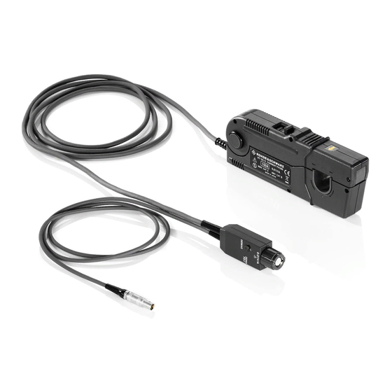
® Product Description R&S RT-ZC10 Inspecting the Contents Product Description Product Overview The R&S RT-ZC10 is an AC/DC current probe. It allows the user to make current measurements from DC to 10 MHz. By clamping on the conductor to be mea- sured, the current waveform is captured easily without interrupting the electric cir- cuit. -
Page 11: Description Of The Probe
® Product Description R&S RT-ZC10 Description of the Probe The following accessories are delivered with the probe: ● User manual ● Carrying case ● R&S RT-Zxx data sheet ● Calibration certificate ● Documentation of calibrated values Description of the Probe 1 = Sensor head (clamp) 2 = Sensor 3 = Slider... - Page 12 ® Product Description R&S RT-ZC10 Description of the Probe 11 = Terminator 12 = Power supply cable 13 = Sensor cable Sensor head The sensor head clamps on the conductor being measured, and carries out the actual current measurement. It is a precision assembly including a molded com- ponent, a ferrite core, and a Hall effect element.
-
Page 13: Putting Into Operation
® Putting into Operation R&S RT-ZC10 Preparing the Measurement Putting into Operation Preparing the Measurement Voltage check When using a different power supply than the R&S RT-ZA13 probe power supply, before turning on the power, make sure that the voltage of the used power supply matches the supply voltage indicated in the data sheet "R&S RT-Zxx high voltage and current probes". - Page 14 ® Putting into Operation R&S RT-ZC10 Preparing the Measurement 4. Check that the conductor being measured is not clamped when supplying power to the R&S RT-ZC10. When power is turned on, a demagnetizing wave- form is initially applied to the output. This is intentional in the design, and not a fault.
-
Page 15: Connecting The Probe To The Oscilloscope
® Putting into Operation R&S RT-ZC10 Connecting the Probe to the Oscilloscope Connecting the Probe to the Oscilloscope ► Connect the probe box (1) to the Rohde & Schwarz probe interface of the oscilloscope (2). The probe snaps in when connected properly to the port. Figure 3-2: Connecting the probe to the Rohde &... -
Page 16: Demagnetizing And Zero Adjustment
® Putting into Operation R&S RT-ZC10 Demagnetizing and Zero Adjustment Demagnetizing and Zero Adjustment Risk of circuit damage ● Do not demagnetize while the R&S RT-ZC10 is clamping a conductor to be measured. Demagnetizing causes current to flow into the conductor, which may damage parts in the circuit to be measured. -
Page 17: Connecting The Probe To The Dut
® Putting into Operation R&S RT-ZC10 Connecting the Probe to the DUT 5. Press the slider on the sensor head until the UNLOCK indication disappears, and hold it until LOCK appears. Check that the opening lever is firmly locked and the clamp is securely closed. 6. - Page 18 ® Putting into Operation R&S RT-ZC10 Connecting the Probe to the DUT Check, if the opening lever is firmly locked and the clamp is securely closed. If the sensor head is not properly closed, accurate measurement is not possible. The current consumption of clamp-on probes depends on the current to be measured.
- Page 19 ® Putting into Operation R&S RT-ZC10 Connecting the Probe to the DUT Risk of instrument damage due to continuous input current ● The maximum continuous input range is based on heat that is internally generated during measurement. Always keep the input current below this level.
- Page 20 ® Putting into Operation R&S RT-ZC10 Connecting the Probe to the DUT Risk of instrument damage due to continuous input current ● At high ambient temperatures, the built-in safety circuit may activate at current input levels below the rated continuous maximum current. ●...
- Page 21 ® Putting into Operation R&S RT-ZC10 Connecting the Probe to the DUT ● Immediately after powering on, this device may be subject to an appre- ciable offset drift due to the effect of self-heating. To counteract this, allow the device to warm up for about 30 minutes before carrying out measurements.
-
Page 22: Maintenance And Service
® Maintenance and Service R&S RT-ZC10 Contacting Customer Support Maintenance and Service If service or calibration is needed, contact your Rohde & Schwarz service center. Return a defective product to the Rohde & Schwarz service center for diagnosis and exchange. Cleaning 1. -
Page 23: Returning For Servicing
® Maintenance and Service R&S RT-ZC10 Calibration Interval Figure 4-1: QR code to the Rohde & Schwarz support page Returning for Servicing Use the original packaging to return your R&S RT-ZC10 to your Rohde & Schwarz service center. A list of all service centers is available on: www.services.rohde-schwarz.com If you cannot use the original packaging, consider the following: 1. -
Page 24: Discarding The Product
® Maintenance and Service R&S RT-ZC10 Discarding the Product Discarding the Product Handle and dispose the product in accordance with local regulations. User Manual 1409.7808.02 ─ 03... -
Page 25: S Rt-Za13 Probe Power Supply
® R&S RT-ZA13 Probe Power Supply R&S RT-ZC10 R&S RT-ZA13 Probe Power Supply This unit is a special-purpose power supply for the current probes. You can connect up to four current probes to the power supply. Front view Rear view User Manual 1409.7808.02 ─...
Need help?
Do you have a question about the R&S RT-ZC10 and is the answer not in the manual?
Questions and answers