Advertisement
Available languages
Available languages
Quick Links
All manuals and user guides at all-guides.com
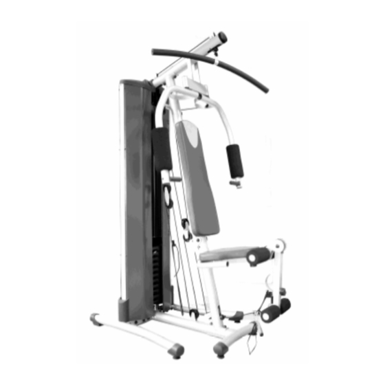
G119T / G119AT
Instrucciones de montaje y utilización
Instructions for assembly and use
Instructions de montage et utilisation
Montage und gebrauchsanleitung
Instruções de montagem e utilização
Istruzioni di montaggio e uso
Montage-en gebruiksinstrukties
Advertisement

Related Manuals for BH G119T


Summary of Contents for BH G119T
- Page 1 All manuals and user guides at all-guides.com G119T / G119AT Instrucciones de montaje y utilización Instructions for assembly and use Instructions de montage et utilisation Montage und gebrauchsanleitung Instruções de montagem e utilização Istruzioni di montaggio e uso Montage-en gebruiksinstrukties...
- Page 2 All manuals and user guides at all-guides.com Fig. 1...
- Page 3 All manuals and user guides at all-guides.com Fig. 1A Fig. 2 Fig. 2A Fig. 3...
- Page 4 All manuals and user guides at all-guides.com Fig. 4 Fig. 4A Fig. 5 Fig. 5A...
- Page 5 All manuals and user guides at all-guides.com Fig. 6 Fig. 7 Fig. 8...
- Page 6 All manuals and user guides at all-guides.com Fig. 9 Fig. 9A Fig. 10 Fig. 11...
- Page 7 All manuals and user guides at all-guides.com Fig. 12 Fig. 12A Fig. 13 Fig. 14 Fig. 15 Fig. 16...
- Page 8 All manuals and user guides at all-guides.com Fig. 17 Fig. 18 Fig. 19...
- Page 9 All manuals and user guides at all-guides.com Fig. 20 Fig. 20A Fig. 21 Fig. 22...
- Page 10 All manuals and user guides at all-guides.com Fig. 22A Fig. 23 Fig. 24...
- Page 11 All manuals and user guides at all-guides.com Fig. 25 Fig. 26 Fig. 27...
- Page 12 All manuals and user guides at all-guides.com Fig. 28 Fig. 29 Fig. 30 Fig. 31...
- Page 13 All manuals and user guides at all-guides.com Fig. 32 Mod. G-119T Mod.G-119AT...
-
Page 14: Instrucciones De Montaje
All manuals and user guides at all-guides.com Español INSTRUCCIONES DE (65) Espumas largas. (66) Espumas superiores soporte MONTAJE.- piernas. Saque unidad caja (67) Espumas inferiores soporte compruebe que tiene todas las piezas. piernas. Para el montaje de esta máquina, (43) Tapas embellecedoras cuerpo se recomienda la ayuda de una principal. - Page 15 All manuals and user guides at all-guides.com 4.-Coloque el cuerpo principal (F) en la giro de brazos Fig.10. base tal como indica la Fig.4. Coloque Continuación coloque la chapa (98) los tornillos y la placa (95), solamente con el logo hacia fuera, y monte los apuntando sin apretar Fig.4A.
- Page 16 All manuals and user guides at all-guides.com MONTAJE DEL ASIENTO.- Suelte el tornillo del soporte tensor de cable (G) y sujete el cable con el 15 -Coja el asiento (34) y posiciónelo tornillo Fig.20 A. en el soporte asiento Fig.15. Coja los tornillos (85) y las arandelas Nota: Al transcurrir un tiempo, es (91) y atorníllelo.
- Page 17 (42). Fig.31. colocado y que no salga del tubo selector de pesas. Para retirar la BH SE RESERVA EL DERECHO A varilla, gírela en el sentido de las MODIFICAR ESPECIFICA- agujas del reloj y tire de ella.
- Page 18 All manuals and user guides at all-guides.com English 1. ASSEMBLY INSTRUCTIONS.- NUTS & BOLTS (85) Bolts M-6x20. Take the unit out of its box and make (97) Bolts M-6x12. sure that all of the pieces are there: (91) Flat washers M-6. The assistance of a second person is (86) Bolts M-6x8.
-
Page 19: Fitting The Backrest
All manuals and user guides at all-guides.com 6.-Remove the screws (83) from the FITTING THE BACKREST.- guide tubes (E) Fig.6 and position the backrest (33) 12.-Take guide tubes as shown in Fig.6A. position it against the central mast, as shown in Fig.12. 7.-Next, place the weights (50) onto Now use the bolts (85) and washers the guide tubes as shown in Fig.7,... -
Page 20: Fitting The Panels
All manuals and user guides at all-guides.com A).-Take the end of the steel cable the upper part as shown in Fig.24. (11) Fig.17 and open the carabiner on Also fix these plates onto the lateral the weight selector post (47), connect tubes, pressing hard on the black it Fig.18 and tighten the carabiner. - Page 21 (29) and lift it in the direction of the arrow as shown in Fig.30. The same rod is used to put the seat back up. BH RESERVES THE RIGHT TO MODIFY THE SPECIFICATIONS OF Note: The seat can be put into two ITS PRODUCTS WITHOUT PRIOR different positions.
-
Page 22: Montage
All manuals and user guides at all-guides.com Français 1 MONTAGE.- (43) Caches pour le corps principal. (44) Bouchons en mousse. Déballer l’appareil et vérifier qu’il ne (96) Plaque support. manque aucune pièce. Pour monter cette machine, il est VISSERIE: vivement recommandé de se faire (85) Vis de M-6x20. - Page 23 All manuals and user guides at all-guides.com 5.-Placer le corps supérieur (K) Fig.5 MONTAGE MOUSSES corps principal SUPÉRIEURES.- introduisant la pointe du câble dans le 11.-Prendre les mousses (65) et les trou (M). Vissez un peu les écrous introduire dans les deux tubes de comme indiqué...
- Page 24 All manuals and user guides at all-guides.com MONTAGE MOUSSES l’assise de celui-ci. Pour y remédier, il suffira de tendre le câble en acier INFÉRIEURES.- dans le tendeur (G). 16.-Prendre d’abord les mousses (66) et les introduire dans les tubes ronds 18.-Introduire la chaîne du câble en supérieurs du support jambes, Fig.16, acier (50) dans le crochet (51) de...
- Page 25 (42) Fig.31. Afin d’optimiser l’exercice, des lettres sont indiquées sur les poids. En BH SE RÉSERVE LE DROIT DE MODIFIER CARACTÉRISTI- consultant les barèmes d’équivalence QUES DE SES PRODUITS SANS Fig.32 placés sur le socle de la...
- Page 26 All manuals and user guides at all-guides.com Deutsch 1. MONTAGEHINWEISE.- Beine. (67) Untere Schaumstoffe Auflager Nehmen Sie die Einheit aus dem Beine. Karton und vergewissern Sie sich, (43) Zierdeckel Hauptkörper; dass kein Teil fehlt. (44) Deckel Schaumstoffe . Zur Montage dieser Maschine wird (96) Unterstützung Platte.
- Page 27 All manuals and user guides at all-guides.com Sie dabei auf die vertikale Position der Dreharmlehnen Fig.10. Hauptstruktur (F) Fig.4. Bringen Sie anschließend das Blech (98) mit dem Logo nach Außen an und 5.- Bitte platzieren Sie den oberen dann die Schrauben zusammen mit Körper (11) (Zeichnung 5) in den den Unterlegscheiben und Schrauben, Hauptkörper (1);...
- Page 28 All manuals and user guides at all-guides.com Sitzrohrs Fig.14 ein. Unterlegschraube wieder auf. Nehmen Sie den Knauf (31) und C).- Nehmen Sie das Ende des richten Sie ihn an den Löchern Kabels und stecken Sie es durch die zwischen den Rohren aus, ziehen Sie erste Rolle (100), wie in der Fig.20 ihn im Uhrzeigersinn an.
- Page 29 24.-Wenn der Keil des Hakens das Loch des Auswahlrohres (21) für die Gewichte passiert, drehen Sie den BH BEHÄLT SICH DAS RECHT Keil (P) gegen den Uhrzeigersinn, so VOR, DIE SPEZIFIKATIONEN DES dass er in die Position kommt, wie in...
-
Page 30: Instruções De Montagem
All manuals and user guides at all-guides.com Português 1. INSTRUÇÕES DE (32) Arandelas de amortização de pesos. MONTAGEM.- (69) Faixa apoio de mão. Retire a unidade da caixa e verifique (65) Espumas longas. se tem todas as peças. (66) Espumas superiores suporte Para a montagem desta máquina,... - Page 31 All manuals and user guides at all-guides.com 4.-Coloque o corpo principal (F) na De seguida, coloque a chapa (98) base como indica a Fig.4. Coloque os com o logotipo para fora, e monte os parafusos (95), apenas apontando parafusos juntamente sem apertar Fig.4A.
- Page 32 All manuals and user guides at all-guides.com MONTAGEM DO ASSENTO.- pela terceira roldana (102) Fig.20. Solte o parafuso do suporte tensor de assento (34) 15.-Pegue cabo (G) e aperte o cabo com o posicione-o suporte assento parafuso Fig.20 A. Fig.15. Pegue nos parafusos (85) e nas Nota: Ao fim de um tempo, é...
- Page 33 (42) Fig.31. que o selector está bem colocado e que não sai do tubo selector de pesos. Para retirar a varilha, gire-a no A BH RESERVA-SE O DIREITO DE sentido dos ponteiros do relógio e MODIFICAR AS ESPECIFICAÇÕES puxe-a.
-
Page 34: Istruzioni Di Montaggio
All manuals and user guides at all-guides.com Italiano 1. ISTRUZIONI DI (67) Imbottiture inferiori supporto gambe. MONTAGGIO.- (43) Coperchi decorativi corpo Disimballare l'unità e verificare che vi principale. siano tutti i pezzi. (44) Coperchietti delle imbottiture. montaggio questa (96) Lamiero di supporto. macchina, si raccomanda l’ausilio di una seconda persona. - Page 35 All manuals and user guides at all-guides.com 5.-Inserire il corpo superiore (K) Fig.5 MONTAGGIO DELLE nel corpo principale (A), inserendo la IMBOTTITURE SUPERIORI.- punta del cavo dal foro (M). Stringere 11.-Prendere le imbottiture (65) ed leggermente i dadi come si indica inserirle nei due tubi per l’esercizio del nella Fig.5A.
-
Page 36: Montaggio Del Telaio
All manuals and user guides at all-guides.com MONTAGGIO DELLE Nota: Trascorso un certo periodo di IMBOTTITURE SUPERIORI.- tempo, è possibile che si noti una 16.-Innanzi tutto prendere leggera distensione cavo imbottiture (66) ed inserirle nei tubi acciaio, per il posizionamento del rotondi superiori del supporto gambe cavo. - Page 37 Fig.29. Per ritirare la barretta, la giri nel senso delle lancette dell’orologio e la tiri. Per un miglior controllo dell’ esercizio, BH SI RISERVA IL DIRITTO DI i pesi sono consegnati marcati con MODIFICARE LE SPECIFICAZIONI lettere.
-
Page 38: Montage Instructies
All manuals and user guides at all-guides.com Nederlands 1. MONTAGE INSTRUCTIES.- (44) Schuimafdekkingen. (96) Ondersteuning plaat. Haal het toestel uit de doos en controleer of alle onderdelen er zijn: MOEREN & SCHROEVEN De hulp van een tweede persoon (85) Schroeven M-6x20. wordt aanbevolen bij het monteren (97) Schroeven M-6x12. - Page 39 All manuals and user guides at all-guides.com 5.-Bevestig het bovenframe (K) Fig.5 opnieuw vast. op het hoofdframe (A) door het Draai de schroeven goed aan. uiteinde van de kabel door het gat (M) te steken. Maak de moeren met de DE SCHUIMAFDEKKINGEN hand vast zoals weergegeven in VAN DE BOVENKANT...
- Page 40 All manuals and user guides at all-guides.com de twee buizen op één lijn plaatsend. door het tweede, onderste katrol (101) Fig.20. HET ZADEL BEVESTIGEN.- Ga door met het halen van het kabeluiteinde door het derde katrol 15.-Neem het zadel (34) en plaats het (102) Fig.20.
- Page 41 All manuals and user guides at all-guides.com 21.- Plaats de bovenafscherming (51) controleren zijn de gewichten van bovendeel letters voorzien. Op de tabel Fig.32 op hoofdonderdeel (A) Fig.26. Breng nu het voetstuk van het apparaat kunt u al stevig duwend (97) om de beurt de de bijbehorende krachtin-spanning in zwarte onderdelen aan.
- Page 42 All manuals and user guides at all-guides.com...
- Page 43 All manuals and user guides at all-guides.com Para pedido de repuesto: Indicar el modelo de la máquina Nº correspondiente a la pieza Cantidad To order replacement parts: State the machine model Corresponding parts Nº Quantity Pour toute commande pièces détachées Indiquer le modèle de la machine Numéro de la pièce Quantité...
- Page 44 SIN PREVIO AVISO. SPECIFICATIONS MAY BE CHANGED WITHOUT PRIOR NOTICE DUE TO OUR PROGRAMME OF CONTINUOUS PRODUCT DEVELOPMENT. BH SE RÉSERVE LE DROIT DE MODIFIER LES SPECIFICATIONS DE SES PRODUITS SANS PRÉAVIS. BH BEHALT SICH DAS RECHT VOR, ÄNDERUNGEN DER MODELL-ANGABEN OHRE VORHERIGE ANKÜNDIGUNG VORZUNEHMEN.
Need help?
Do you have a question about the G119T and is the answer not in the manual?
Questions and answers