Nikon Nivo Series Instruction Manual
Total station
Hide thumbs
Also See for Nivo Series:
- Instruction manual (32 pages) ,
- Communication interface manual (34 pages)

Related Manuals for Nikon Nivo Series


Summary of Contents for Nikon Nivo Series
- Page 1 Total Station Nivo Series Nivo Instruction Manual Version D 1.0.0 Part Number C240E6 March 2014 www.trimble.com...
- Page 2 You are cautioned that changes or modifications not EN300 328v1.7.1, EN50360 satisfied expressly approved by the party responsible for Hereby, Nikon-Trimble Co., Ltd., declares that this instrument is in compliance could void your authority to operate the compliance with the essential requirements and other relevant equipment.
-
Page 3: Safety
Safety In this chapter: Introduction Warnings and Cautions Laser Safety Total Station Nivo Series Instruction Manual... -
Page 4: Introduction
Never look at the sun through the telescope. If you do, you may damage or lose your eyesight. WARNING – Nivo series instruments are not designed to be explosion-proof. Do not use the instrument in coal mines, in areas contaminated with coal dust, or near other flammable substances. -
Page 5: Cautions
CAUTION – Before setting up the tripod, make sure that no-one’s hands or feet are underneath it. When the legs of the tripod are being driven into the ground, they could pierce hands or feet. Total Station Nivo Series Instruction Manual... -
Page 6: Rechargeable Lithium-Ion (Li-Ion) Batteries
– If battery fluid gets into your eyes, immediately rinse your eyes with clean water and seek medical attention. Do not rub your eyes! – If battery fluid gets onto your skin or clothing, immediately use clean water to wash off the battery fluid. Total Station Nivo Series Instruction Manual... -
Page 7: Laser Safety
Laser beam path should be located well above or below eye level wherever practicable. WARNING – When the laser product is not used, it should be stored in a location where unauthorized personnel cannot gain access. Total Station Nivo Series Instruction Manual... - Page 8 635 nm Output power CW Po < 1.0 mW Table 1.2 Conforming standards E.U. IEC60825-1:2007: class 3R FDA21CFR Part 1040 Sec.1040.10 and 1040.11 (except for deviations pursuant to Laser Notice No.50, dated June 24, 2007) Total Station Nivo Series Instruction Manual...
- Page 9 Safety Labels Laser pointer and Distance meter Laser plummet (Option) Total Station Nivo Series Instruction Manual...
- Page 10 Safety Total Station Nivo Series Instruction Manual...
-
Page 11: Table Of Contents
........34 [COD] Total Station Nivo Series Instruction Manual... - Page 12 Recording Measurement Data....... . . 84 Total Station Nivo Series Instruction Manual...
- Page 13 Downloading data ......132 Uploading coordinate data ......133 Total Station Nivo Series Instruction Manual...
- Page 14 Settings ........158 Total Station Nivo Series Instruction Manual...
- Page 15 System Error ........180 Total Station Nivo Series Instruction Manual...
- Page 16 Contents Total Station Nivo Series Instruction Manual...
-
Page 17: Introduction
C H A P T E R Introduction In this chapter: Welcome Parts of the Instrument Maintenance Total Station Nivo Series Instruction Manual... -
Page 18: Welcome
Welcome Thank you for purchasing this Nikon product. This instruction manual was written for the users of Total Station Nivo series instruments. Before you operate a Nivo series instrument, read this manual carefully. In particular, pay attention to the warnings and cautions that appear in the Safety section at the front of the manual. -
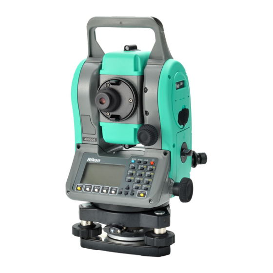
Page 19: Parts Of The Instrument
Introduction 1 Parts of the Instrument Figure 1.1 Figure 1.2 show the main parts of the Nivo series instrument. Carrying handle Optical sight (Finder) Telescope focusing ring Telescope Horizontal axis eyepiece indication mark Diopter ring Vertical tangent screw Reticle plate cover... - Page 20 * The dual display model with Face-2 display / keyboard is also available. Figure shows the single display model. Figure 1.2 Total Station Nivo series – Face-2 Figure shows the clampless model. Total Station Nivo Series Instruction Manual...
-
Page 21: Maintenance
Do not store the Nivo series instrument in hot or humid locations. In particular, • you must store the battery pack in a dry location at a temperature of less than 30 °C (86 °F). - Page 22 • exposed to rain for an extended period. If exposure to rain is unavoidable, make sure that the carrying case is placed with the Nikon nameplate facing upward. The battery pack contains a Lithium-ion battery. When disposing of the battery •...
-
Page 23: Preparation
Sighting Setting the Measurement Mode and Preparing the Target Measurement in Reflectorless mode Preparing the Reflector Sheet Setting Up the Prism Reflector Face-1/Face-2 Measurements (For dual display) Total Station Nivo Series Instruction Manual... -
Page 24: Unpacking And Packing The Instrument
Preparation Unpacking and Packing the Instrument Note – Handle the Nivo series instrument gently to protect it from shocks and excessive vibration. Unpacking To unpack the instrument, grip the carrying handle and gently remove the instrument from the carrying case. - Page 25 Before storing the battery pack or battery charger, cover the contact points with insulation tape. If you do not cover the contact points, the battery pack or charger may short circuit, causing fire, burns, or damage to the instrument. Total Station Nivo Series Instruction Manual...
- Page 26 Charging may take 2-4 hours if the battery was normally discharged. • Charging may take up to 5 hours with a completely drained battery which has • been stored for several months without use. Total Station Nivo Series Instruction Manual...
- Page 27 If the case temperature continues to get too hot internally even after • temperature regulation is enabled, there is a secondary failsafe which will abort the calibration completely. If an abort occurs, the calibration light(s) will blink rapidly and battery charging will be re-enabled. Total Station Nivo Series Instruction Manual...
-
Page 28: Detaching And Re-Attaching The Battery Pack
Close the battery box cover and turn the knob clockwise until the secure click sound is heard. CAUTION – If the battery box cover is not closed, this could adversely affect the watertightness of the instrument. Total Station Nivo Series Instruction Manual... -
Page 29: Setting Up The Tripod
While supporting the tripod head with one hand, loosen the tripod leg clamps and adjust the lengths of the legs until the air bubble is in the center of the circular level. Tighten the tripod leg clamps. Total Station Nivo Series Instruction Manual... -
Page 30: Centering Using The Laser Plummet
Use only direct movement to center the instrument. Do not rotate it. When the instrument is centered, tighten the mounting screw. – If the displacement of the station point is major, repeat this procedure – from Step 2 Total Station Nivo Series Instruction Manual... -
Page 31: Centering Using A Plumb Bob
If the bubble in the electronic level remains centered, the instrument is level. If the Bottom edge of bubble moves off center, adjust the electronic the keyboard panel level. For detailed instructions, see Adjusting the Electronic Level, page 140. Total Station Nivo Series Instruction Manual... -
Page 32: Sighting
If the target image does move, rotate the telescope focusing ring. Then repeat from Step c. Rotate the tangent screw: The final turn of the tangent screw should be in a clockwise directions, to – align the target accurately on the center crosshairs. Total Station Nivo Series Instruction Manual... -
Page 33: Setting The Measurement Mode And Preparing The Target
As the Nivo series is extremely sensitive, multiple reflections on the prism surface can sometimes cause a significant loss in accuracy. To maintain the accuracy of your measurements: Total Station Nivo Series Instruction Manual... -
Page 34: Measurement In Reflectorless Mode
To measure less reflective objects, use the N-prism (reflectorless) mode Measurement in Reflectorless mode The intensity of the reflection from the target determines the distance the Nivo series can measure in this mode. The color and condition of the target surface also affect the measurable distance, even if the targeted objects are the same. -
Page 35: Preparing The Reflector Sheet
Preparing the Reflector Sheet The reflector sheet can be used for measurements in Prism mode. Assemble the reflector sheet as shown below. Reflector sheet Mini prism adapter Telescopic Prism pole prism pole tripod type PPS Total Station Nivo Series Instruction Manual... -
Page 36: Setting Up The Prism Reflector
If you are using a single prism holder, set the position of the target plate (see page 22). Detailed instructions for Step 2 through Step 5 are provided on the following pages. Note – Nivo series must be used with the Tribrach W30 or W30b. Total Station Nivo Series Instruction Manual... -
Page 37: Adjusting The Height Of The Tribrach Adapter
Adjusting the height of the tribrach adapter The tribrach adapter has a height adjustment adapter. To use the prism reflector with a Nivo series instrument, remove the height adjustment adapter as shown in the Figure below. The height adjustment adapter will be used with other Nikon Total Stations. -
Page 38: Setting The Position Of The Target Plate
A Face-1 measurement is made with the vertical circle positioned to the left of the telescope eyepiece. A Face-2 measurement is made with the vertical circle positioned to the right of the telescope eyepiece. Face-1 Face-2 Total Station Nivo Series Instruction Manual... -
Page 39: Getting Started
C H A P T E R Getting Started In this chapter: Turning the Instrument On and Off Changing Regional Configuration Pre-sets Display and Key Functions List Display Inputting Data Jobs Measuring Distances Total Station Nivo Series Instruction Manual... -
Page 40: Turning The Instrument On And Off
114), the instrument goes into sleep mode. When the instrument is in sleep mode, it wakes up if any of the following occurs: You press a key • The instrument receives a remote control command • Total Station Nivo Series Instruction Manual... -
Page 41: Changing Regional Configuration Pre-Sets
Changing Regional Configuration Pre-sets To provide easier configuration for common regional settings, you can quickly configure the Nikon total station to a pre-set combination of default regional settings. The Regional Configuration screen appears only after the language configuration is complete, the instrument has rebooted. -
Page 42: Display And Key Functions
The default regional configuration pre-set is “United States” settings. For more information, see Settings, page 112. Display and Key Functions The following figure shows the keys on the Nivo series instrument keyboard and the LCD display. Face-1 Face-2 The functions of the Nivo keys are as follows. - Page 43 In numeric mode, enters 5. In alphanumeric mode, enters J, K, L, or 5. Displays RAW, XYZ, or STN data, depending on your page 39 setting. In numeric mode, enters 6. In alphanumeric mode, enters M, N, O, or 6. Total Station Nivo Series Instruction Manual...
- Page 44 [MSR1] displays the result. When the menu or list is displayed, moves the cursor to the next item. (Face-2) Functions the same as on the Face-1 keyboard [REC/ENT] has been pressed. Total Station Nivo Series Instruction Manual...
-
Page 45: Status Bar
When you display observation data, the EDM measurement status shows the mode that was used when the data was collected. Reflectorless mode Communication port status (This is only available when the optional Bluetooth is installed. See Optional Bluetooth function, page 133.) Bluetooth enabled Total Station Nivo Series Instruction Manual... - Page 46 Internal batteries (above: Left battery, below: Right battery) External battery Internal External battery battery Battery level indication : Battery low If the battery level becomes critically low, the message on the right appears: Total Station Nivo Series Instruction Manual...
-
Page 47: Lcd Backlight, Laser Pointer, Beep Sound And Contrast Adjustment
To close the window, press [ESC] 1. LCD backlight LCD backlight is OFF LCD backlight is ON 2. Laser pointer Laser pointer is OFF Laser pointer is ON 3. Sound Sound is OFF Sound is ON Total Station Nivo Series Instruction Manual... -
Page 48: [Dsp] Key
The items that you can choose from are HA, AZ, HL, VA, V%, SD, VD, HD, Z, and (none). Total Station Nivo Series Instruction Manual... -
Page 49: [Mode] Key
The input mode indicator in the status bar changes to show the current input mode. When the cursor is in a height (HT) field, only numeric input mode is available. Pressing [MODE] has no effect when the cursor is in a HT field. Total Station Nivo Series Instruction Manual... -
Page 50: [Cod] Key
Setting the default code When you press in the BMS, a window for [COD] entering the feature code appears. You can use the softkeys to enter the List Stack code. Total Station Nivo Series Instruction Manual... -
Page 51: [Hot] Key
The ppm value is updated automatically. Selecting the target set A target set specifies settings for the target type, the prism constant, and height of target. When you change the selected target set, all three settings are changed. Total Station Nivo Series Instruction Manual... - Page 52 To display a list of previously used notes, press the softkey. The stack stores the last 20 notes. Stack to highlight a note in the list. Then press to select the note. [ENT] (Laser plummet is on.) Total Station Nivo Series Instruction Manual...
-
Page 53: Bubble Indicator
To display the bubble indicator in an observation screen, press The Nivo series has two-axis level compensation. To turn the leveling compensators on or off, press [<]... -
Page 54: [Usr] Keys
The currently assigned function is indicated by an asterisk (*) beside the function name. To change the function that assigned to the key, press to highlight the function. Then press [ENT] Total Station Nivo Series Instruction Manual... -
Page 55: [Dat] Key
Select Format screen. Use this screen to change the type of data that is assigned to . Press or select DAT [MENU] [DAT] display the Data menu whenever you press [DAT] Total Station Nivo Series Instruction Manual... -
Page 56: List Display
The default name for a new point is the last point name entered, with the last digit incremented. For example, if the last point name was A100, the default name for the next point is A101. Total Station Nivo Series Instruction Manual... - Page 57 (the CD field) to store the [ENT] point in the current job. Pressing without a point name [ENT] To use a point without recording the coordinates, press in a PT field, without entering a point name. [ENT] Total Station Nivo Series Instruction Manual...
- Page 58 To change [MSR1] [MSR2] the height of the target, press the softkey. To go to the point recording screen when you have finished the measurement, press [ENT] Enter the point or code name. Press [ENT] Total Station Nivo Series Instruction Manual...
- Page 59 Then press [ENT] When you return to the point input screen, the selected point name is entered in the PT field. You can add digits or alphabetic characters if required. Total Station Nivo Series Instruction Manual...
-
Page 60: Entering A Code
MENU > Data > Code . For more information, see Editing an item in the List point list or code list, page 130. to highlight the feature code that you want to use. Then press [ENT] Total Station Nivo Series Instruction Manual... -
Page 61: Advanced Feature: Searching For A Code By Using The First Character
Press the Edit softkey to change the Qcode. You can edit the entire code, or just the number at the end of the code. You can still use [DSP] to change the background displays. Total Station Nivo Series Instruction Manual... -
Page 62: Entering Values In Feet And Inches
If the denominator is 16, it is not shown on the screen. Jobs To record data on the instrument, you must create or open a job. Tip – Before you use the instrument for the first time, check the job settings. Total Station Nivo Series Instruction Manual... -
Page 63: Creating A New Job
If the point is found in the control job, the selected point is copied to the current job as a UP record. Total Station Nivo Series Instruction Manual... -
Page 64: Measuring Distances
For information on how to assemble the prism reflector, see Setting Up the Prism Reflector, page Total Station Nivo Series Instruction Manual... -
Page 65: Measuring Distances
(T-P corr, Sea Level, C&R corr., and Map projection) are included in the job settings. These settings are job-specific. If you need to change any of these settings, you must create a new job. For more information, see Job settings, page 97, and Settings, page 112. Total Station Nivo Series Instruction Manual... -
Page 66: Measurement Settings
A measurement made immediately after changing the target setting may take a longer time than usual.The Target setting is used to apply better cyclic-error adjustment in distance measurement. It efficiently eliminates multipath reflection. Total Station Nivo Series Instruction Manual... - Page 67 The Confirm setting displays the Record PT screen before data is recorded. The ALL setting is a quick shooting and recording mode. The instrument automatically records the point using the default PT/CD. The instrument then returns to the BMS for the next measurement. Total Station Nivo Series Instruction Manual...
- Page 68 Getting Started Total Station Nivo Series Instruction Manual...
-
Page 69: Applications
C H A P T E R Applications In this chapter: HA Reset and Angle Operations Station Setup Stakeout Program Key Recording Measurement Data Measuring Offsets Total Station Nivo Series Instruction Manual... -
Page 70: Ha Reset And Angle Operations
To end repeat angle measurement, press [ESC] When you have accumulated enough horizontal angle between the backsight and the foresight, press ] or to take a measurement to [MSR1 [MSR2] the foresight. Total Station Nivo Series Instruction Manual... -
Page 71: Face-1/Face-2 Measurement
To record the averaged HA, VA, and SD from the F1/F2 data, press [ENT] or the softkey and select the CP or SS record type. For the HA to be adjusted from a F1/F2 measurement, the Backsight must also have been measured in F1/F2 during the station setup. Total Station Nivo Series Instruction Manual... -
Page 72: Horizontal Angle Hold
CD field, the new [ENT] point is stored. If the specified point has a code, the code – appears in the CD field. Enter the instrument height in the HI field and then press [ENT] Total Station Nivo Series Instruction Manual... - Page 73 QA screen. The [DSP] QA screen shows the dHD and dVD values, which indicate the difference between the measured distance and the distance calculated from the known coordinates. To record the station, press [ENT] Total Station Nivo Series Instruction Manual...
-
Page 74: Advanced Feature: Measuring F1 And F2
Sighting the backsight by entering the azimuth angle Backsight point Azimuth Station point (Xi, Yi, Zi) To enter the azimuth angle to the backsight point, press or select in the Backsight Angle screen. Total Station Nivo Series Instruction Manual... -
Page 75: Setting Up A Station Using Multiple Point Resection
You can use a maximum of 10 points in a resection. Measurements can be distance and angle, or angle only. Calculation starts automatically when enough measurements are taken. You can delete poor observations and recalculate if necessary. You can also select the BS point Total Station Nivo Series Instruction Manual... - Page 76 To proceed to the next point, press [ENT] Enter the second point (PT2) and its height of target. Measure to PT2 and press [ENT] When the instrument has enough data, it calculates the station (STN) coordinates. Total Station Nivo Series Instruction Manual...
- Page 77 If you use a distance shot, the distance between the target points must be greater than the measured distance. Stn-Z is calculated from distance-measured data. If no distances are measured, then Stn-Z is calculated using angle-only measurements to points with 3D coordinates. Total Station Nivo Series Instruction Manual...
-
Page 78: Advanced Feature: Viewing And Deleting A Measurement In Resection
No default PT is assigned to the BS. Leave this field blank, or enter a BS point name. The backsight azimuth (AZ) defaults to zero, but you can change this. To complete the station setup, sight the BS and press [ENT] Total Station Nivo Series Instruction Manual... -
Page 79: Determining Station Elevation
To record the updated STN, press [ENT] When the HI is changed, the Z coordinate is updated before the station is recorded. You must complete a station setup before you use the Remote Benchmark function. Total Station Nivo Series Instruction Manual... -
Page 80: Checking And Resetting The Backsight Direction
To enter the Base XYZ function, press select in the Stn Setup menu. Base XYZ The current instrument XYZ values are shown as the default. Enter the new instrument XYZ values and press [ENT] Total Station Nivo Series Instruction Manual... -
Page 81: Two-Point Resection Along A Known Line
If you select , the azimuth input By Angle screen appears. Enter the angle value and press [ENT] A measurement screen appears. Sight P2 and press to take a [MSR1] [MSR2] measurement. Press [ENT] Total Station Nivo Series Instruction Manual... - Page 82 Change 10. To finish the setup and record the station, press in the BS field. [ENT] Sample records CO, Temperature:20C Pressure:1013hPa Prism:0 … ST,9005, ,265, ,1.2350,150.40300,150.40300 F1,265,1.6040,79.0010,90.30150,89.35260, F1,200,1.4590,50.2300,269.4035,93.50110, CO, P1-P2 HD=122.0350 VD=0.5600 Total Station Nivo Series Instruction Manual...
-
Page 83: Stakeout
[ENT] Horizontal distance from station point to stakeout point Vertical distance from station point to stakeout point Horizontal angle to stakeout point If you press [ENT] without entering HA, the current HA is used. Total Station Nivo Series Instruction Manual... - Page 84 (S-O7, or S-O8 if the secondary distance unit is set), the S-O1 screen appears. To customize the S-O2, S-O3, and S-O4 screens, hold down for one second. For [DSP] more information, see Customizing items in the Basic Measurement Screen (BMS), page Total Station Nivo Series Instruction Manual...
-
Page 85: Specifying The Stakeout Point By Coordinates
When the target is on the intended position, the displayed errors become 0.000 m (or 0.000 ft). Difference in horizontal angle to the target point Right/Left (Lateral error) IN/OUT In/Out (Longitudinal error) CUT/FILL Cut/FilL Total Station Nivo Series Instruction Manual... -
Page 86: Advanced Feature: Specifying A Stakeout List By Range Input
To input points by range, press the Fr/To softkey in the PT field. Enter the start point (Fr) and the end point (To). The range between Fr and To must be less than 1001 points. Total Station Nivo Series Instruction Manual... -
Page 87: Divline S-O
The observation screen for the first stake (from the instrument) appears. Sight the prism and press [MSR1] [MSR2] to change the guide point. You can calculate and guide up to double the number of the stakes. Total Station Nivo Series Instruction Manual... -
Page 88: Refline S-O
If you press [ENT] without entering a PT name, you can enter temporary coordinates which are not recorded in the job. Alternatively, press the MSR softkey to measure a point. Enter the second point (P2) of the line. Total Station Nivo Series Instruction Manual... -
Page 89: Program Key
Measuring distance and offset values along a specified line Press or select in the 2Pt RefLine Programs menu. Enter the first point for the reference line. Alternatively (to enter the point by measuring), press the softkey. MsrPT Total Station Nivo Series Instruction Manual... - Page 90 [MSR1] [MSR2] Horizontal distance from P1 to the measure point along the P1-P2 line Horizontal offset from the P1-P2 line to the measured point Vertical offset from the P1-P2 line to the measured poin Total Station Nivo Series Instruction Manual...
-
Page 91: Measuring Distance And Offset Values On The Arc-Curve
Press or select in the Arc RefLine Programs menu. Enter the start of the curve point (P1) and the azimuth of its tangent line (AZ1). To enter P1 by direct measurement, press the softkey. Total Station Nivo Series Instruction Manual... - Page 92 When all factors have been entered, the instrument calculates the curve. If the curve length (Len) is too large for a circle of the given radius, it is shortened. To ... Press ... switch between display screens [DSP] change HT [HOT] record points [ENT] Total Station Nivo Series Instruction Manual...
- Page 93 (ARC4 or ARC5), the ARC1 screen appears. To record the point, press on any observation [ENT] screen. The arc is stored in comment records. Sample records CO,Arc P1:583 AZ1=0.0000 P2:102 AZ2=311.2932 Radius=50.0000 Length=125.6637 Sta= -12.6876 Offset= 1.3721 dZ= 0.0971 SS,17,1.0000,6.9202,18.4700,80.3120,15:48:48,2REF-LINE Total Station Nivo Series Instruction Manual...
-
Page 94: Remote Distance Measurement
Measuring between the current and the first point measured To enter the RDM (Radial) function, press select in the Programs menu. RDM(Radial) Sight the first point and press [MSR1] [MSR2] The distance from the station point to the first point appears. Total Station Nivo Series Instruction Manual... - Page 95 Data that you save in RDM functions is stored in RM records. For more information, see RM records, page 120. When you download data in Nikon RAW format, they are output as comment (CO) records. Measuring between the current point and the immediately preceding point To enter the RDM (Continuous) function, press or select in the Programs menu.
-
Page 96: Measuring Remote Elevation
(target) point Sighting point Station point To enter the Remote Elevation Measurement function, press or select in the Programs menu. Enter the height of target. Sight the target point and press [MSR1] [MSR2] Total Station Nivo Series Instruction Manual... -
Page 97: Measuring Distance And Offset Values On The Vertical Plane
To enter the point by direct measurement, press softkey. MsrPT When you press the softkey, a temporary observation screen appears. Press . The Record PT screen [MSR1] [MSR2] appears. Enter a value in the PT and CD fields. Press [ENT] Total Station Nivo Series Instruction Manual... - Page 98 (PLN3), the PLN1 screen appears. To record the point, press on any screen (V- [ENT] PLN1/3 to V-PLN3/3). Enter PT and CD. Then press [ENT] Sample records CO,Vertical Ref Plane Pt1:516-A1 Pt2:530 CO,Sta=68.021 dz=17.459 SS,30123-A48,1.5480,16.4020,40.4720,89.0730,14:22:47, Total Station Nivo Series Instruction Manual...
-
Page 99: Measuring Distance And Offset Values On The Slope
V-Pln function, but the indicating factors are Sta and dZ, not a and b. For more information, see Measuring distance and offset values on the vertical plane, page Total Station Nivo Series Instruction Manual... -
Page 100: Recording Measurement Data
You can also use the code list or the code stack. For more information, see Entering a code from the code list, page 44, and Entering a code from the stack, page Total Station Nivo Series Instruction Manual... -
Page 101: Outputting Data To The Com Port
Comm page 115. To output data on the COM port when you press [ENT], set the Data Rec field in MENU > Settings > Rec to COM. For more information, see Recording, page 116. Total Station Nivo Series Instruction Manual... -
Page 102: Measuring Offsets
Applications Sample output records through COM port When the Ext.Comm field is set to NIKON: TR PN: PT8 SD:000066626 HA:003856010 VA:008048500 HT:0000061757 (TR PN: point name SD HA VA HT; when ACK is returned, PN is incremented.) When the Ext.Comm field is set to SET:... -
Page 103: Measuring Angle Offsets
Then press [ENT] to record the measured distance with the updated angle value. If you use this method, the dimension of the angle offset is not stored as a CO record. To store the CO record, use the O/S function. Total Station Nivo Series Instruction Manual... -
Page 104: Two-Prism Pole
To record the point, press or the softkey. [ENT] Sample records SS,14,0.0000,38.9200,271.0350,89.2630,11:04:15,DITCH CO,2Prism O/S: P1-P2= 0.5090( 0.5060) P2-Tgt= 0.5020 Note – In this sample data, 0.5090 is the measured value. 0.5060 is the entered value. Total Station Nivo Series Instruction Manual... -
Page 105: Extending A Line By Horizontal Angle Offset
. The height of target is fixed to [ENT] 0.0000 for the offset point. Sample records SS, 40, 0.0000, 48.3304, 169.20370, 82.02470, 10:52:37 CO, PT1, 0.0000, 48.3020,169.19165, 83.58565 CO, PT2, 0.0000, 48.3155,168.54250, 85.42440 CO, O/S MSR:40 0.0000 0.0000 169.20370 87.02340 Total Station Nivo Series Instruction Manual... -
Page 106: Entering A Horizontal Distance After An Angle-Only Shot
Enter the HD. Usually this is the taped distance from the instrument point. Enter a PT (and CD) value and press [ENT] The target point is calculated and recorded as an SS record. Sample records SS,158,0.0000,77.0518,62.08380,108.06510,11:51:48, CO, Input HD:76.1243 Total Station Nivo Series Instruction Manual... -
Page 107: Calculating A Corner Point
(P1-P2 and P3-P4). The default elevation is given by P4. Enter a PT (and CD) value. The height of target (HT) defaults to the value used in the last measurement. To record the corner point, press [ENT] Total Station Nivo Series Instruction Manual... -
Page 108: Measuring Circle Offsets
If you have taken a distance measurement to the center of the circle, press the Calc softkey to calculate the offset using one edge angle observation. Sight the other edge of the circle and press [ENT] Total Station Nivo Series Instruction Manual... -
Page 109: Extending The Slope Distance
Enter the slope distance that you need to add or subtract. You can enter any value from –99.990 through +99.990 m (–328.000 through +328.000 ft). To record the point, press [ENT] Sample records SS,83,1.5000,77.0518,62.08380,81.06510,11:51:48, CO,O/S MSR:83 1.5555 76.5518 62.08380 81.06510 Total Station Nivo Series Instruction Manual... - Page 110 Applications Total Station Nivo Series Instruction Manual...
-
Page 111: Menu Key
C H A P T E R Menu Key In this chapter: Introduction Job Manager Cogo Settings Data Communication 1sec-Keys Calibration Time Total Station Nivo Series Instruction Manual... -
Page 112: Introduction
Press to open the highlighted job. [ENT] When you open a job, all job settings are automatically changed to match those used in the open job. Total Station Nivo Series Instruction Manual... -
Page 113: Creating A New Job
If you select US-Ft or I-Ft, an additional settings screen appears. Use this screen to specify whether to display values in Decimal-Ft or Ft-Inch. VA zero Zenith/Horizon/Compass AZ zero North/South Order NEZ/ENZ Azimuth/0 to BS Total Station Nivo Series Instruction Manual... -
Page 114: Deleting A Job
A control job has the same format as a standard job. You can open and modify it like any other job, and you can use it to record any measured data. To set the control job: Highlight the job that you want to use. Press the softkey. Ctrl Total Station Nivo Series Instruction Manual... -
Page 115: Displaying Job Information
Free space indicates how many points can be stored in the job. To return to the job list, press any key. Total Station Nivo Series Instruction Manual... -
Page 116: Cogo
[ENT] point on the spot to use it in the calculation. The azimuth, horizontal distance, and vertical distance from the first point to the second point are displayed. 10 0 Total Station Nivo Series Instruction Manual... - Page 117 After the measurement, a recording point screen appears. To store the measured point, enter the PT, HT, and CD values and press [ENT]. To use the point without recording it, press [ESC]. Total Station Nivo Series Instruction Manual 1 01...
-
Page 118: Calculating And Manually Inputting Coordinates
If you do not enter a value in the dVD field, the value 0.000 is used. A recording point screen with the calculated coordinates appears. PT defaults to the last recorded PT + 1. Press to store the point. [ENT] 10 2 Total Station Nivo Series Instruction Manual... - Page 119 Input menu. Input XYZ The PT name defaults to the last recorded PT + 1. Enter the coordinates using the numeric keys. To move to the next field, press in a field [ENT] Total Station Nivo Series Instruction Manual 1 03...
-
Page 120: Calculating Area And Perimeter
You must enter the points in the order in which they define the lot. You can enter up to 99 points. Press to store the calculated values as a a comment [ENT] record, or press to return to the Cogo menu. [ESC] 10 4 Total Station Nivo Series Instruction Manual... -
Page 121: Advanced Feature: Entering A Range Of Points
[ENT] When you download data in Nikon RAW format, area (AR) records are output as comment (CO) records. Advanced feature: Entering a range of points To quickly enter a sequential range of points, use the range input function. -
Page 122: Calculating Coordinates From Line And Offset
To calculate the coordinates of the point (PM), press in the dVD field. You can change the Z coordinate [ENT] here. To record the point, press in the CD field. [ENT] 10 6 Total Station Nivo Series Instruction Manual... -
Page 123: Calculating Coordinates Using Intersection Functions
111. Do one of the following: To return to the previous screen, press – [ESC] The calculated value appears in the AZ field. To go to the next screen, press – [ENT] Total Station Nivo Series Instruction Manual 1 07... - Page 124 Enter a point on the line. The line can be defined by two points or by a point and an azimuth. Enter the second point (P2) as the center of the circle. 10 8 Total Station Nivo Series Instruction Manual...
- Page 125 To define the distance (HD) by two points, press softkey. Enter P2 and the distance from P2 (HD). To calculate the coordinates of the intersection point, press in the HD field. [ENT] Total Station Nivo Series Instruction Manual 1 09...
- Page 126 If P1 and P2 are 3D points, the Z coordinate of the perpendicular point is calculated relative to the P1-P2 slope. Enter PT and CD then press to record the [ENT] point. Sample records CO,Int PtLine P1:38 AZ:90.00000+0.00000 CO, P2:506 CC,A-123,,4567.3080,200.1467,-1.2056,POT 11 0 Total Station Nivo Series Instruction Manual...
-
Page 127: Advanced Feature: Entering Angle And Distance Offsets
Enter a negative value to rotate the line counterclockwise. In the O/S field, enter a positive value to specify an offset to the right. Enter a negative value to specify an offset to the left. Total Station Nivo Series Instruction Manual... -
Page 128: Settings
When this field is set to Azimuth, the horizontal angle (HA) that appears and recorded is in Azimuth value. When this field is set to 0 to BS, HA is in HA zero to BS value. 11 2 Total Station Nivo Series Instruction Manual... -
Page 129: Distance
Because the surface of the earth is curved, the vertical difference (VD and Z) at the measurement point, as referenced to the horizontal plane, inevitably includes some error. This error is called curvature error. Also, because the density of the air Total Station Nivo Series Instruction Manual... -
Page 130: Coordinate
The Order and AZ job settings cannot be changed once a job is created. Power saving To open the Power Save menu, press or select in the Settings menu. PwrSave Main Unit OFF/5min/10min/30min Sleep OFF/1min/3min/5min 11 4 Total Station Nivo Series Instruction Manual... -
Page 131: Communications
Decimal-Ft or Ft-Inch. Temp °C (Celsius) °F (Fahrenheit) Press hPa/mmHg/inHg The Angle, Distance, Temp, and Press job settings cannot be changed once a job is created. Total Station Nivo Series Instruction Manual... -
Page 132: Recording
Select Yes to separate the point numbers of station points from other record type point numbers If you set the Split ST field to Yes, an additional setting screen appears. Use this screen to specify the starting ST number. 11 6 Total Station Nivo Series Instruction Manual... - Page 133 Nikon total station to a pre-set combination of default regional settings. For more information, see Changing Regional Configuration Pre-sets, page Tip – The Nikon total station supports up to 3 languages on the instrument. For more information on changing the language settings, see page 117.
-
Page 134: Data
XYZ data, the old raw record becomes raw data only. As a result, only one SS(RAW) record keeps its corresponding SS(XYZ) record. Other SS(RAW) records to the same point no longer have coordinates available. 11 8 Total Station Nivo Series Instruction Manual... - Page 135 When you input a Stn-XYZ by Base-XYZ function, the recorded station appears as a comment record. SY records When you complete a station setup, a SY record is stored. This record contains the Temperature, Pressure, and Prism Constant values. Total Station Nivo Series Instruction Manual...
- Page 136 [DSP] From, To, rHD, and rVD) and the second screen (showing rAZ, rSD, rV%, and rGD). When you download data in Nikon RAW format, RM records are output as comment (CO) records. AR records An AR record stores an area and perimeter calculation.
-
Page 137: Deleting Records
In the RAW screen, use to highlight the record that you want to delete. Then press the softkey. A confirmation screen appears. To delete the selected record, press or the softkey. [ENT] Total Station Nivo Series Instruction Manual 1 21... - Page 138 If the record that you want to delete is referred by an ST record, a confirmation message appears. Deleting station records In the Station screen, use to highlight the record that you want to delete. Then press the softkey. 12 2 Total Station Nivo Series Instruction Manual...
-
Page 139: Editing Records
Do one of the following: In the RAW screen, highlight the record – that you want to edit. Then press the Edit softkey. In the detailed data screen, press the Edit – softkey. Total Station Nivo Series Instruction Manual 1 23... - Page 140 Edit In the detailed data screen, press the Edit – softkey. to highlight a field. Then modify the value in the selected field. To finish editing, press in the CD field. [ENT] 12 4 Total Station Nivo Series Instruction Manual...
- Page 141 The following example shows a comment record for a changed HI value: CO,HI changed at ST:9012 Old HI= 1.345m If you change the BS or AZ values, raw records are not recalculated. A comment record is stored to record the change. Total Station Nivo Series Instruction Manual 1 25...
-
Page 142: Searching Records
Then press to select it. [ENT] Detailed data for the selected record appears. Press the softkey to change the fields shown. Press to return to the list. [ESC] 12 6 Total Station Nivo Series Instruction Manual... - Page 143 Press to select it. [ENT] Detailed data for the selected record appears. Press the softkey to change the fields shown. Press to return to the list. [ESC] Total Station Nivo Series Instruction Manual 1 27...
-
Page 144: Entering Coordinates
For example, you may need to use points named 1, 2, 3 …, as well as points named A1, A2, A3 …. The code list is a prepared list of feature codes. You can use it to store your • own codes. 12 8 Total Station Nivo Series Instruction Manual... - Page 145 [ESC] To delete a whole layer, highlight the layer name in the list and press the DEL softkey. All codes and layers in the selected layer are deleted. Total Station Nivo Series Instruction Manual 1 29...
- Page 146 1155 is stored. If you press the Edit softkey when a layer name appears, only the Lyr field appears. To save changes to the layer name, press [ENT] in the Lyr field. 13 0 Total Station Nivo Series Instruction Manual...
- Page 147 REC field, this value is stored. If you leave the REC field blank, the CD value is stored. Press to add the new code and update the code list. [ENT] Total Station Nivo Series Instruction Manual 1 31...
-
Page 148: Communication
To go to the download settings screen, press or select in the Communication menu. Download Format NIKON SDR2x SDR33 Data Coordinate To display the total number of records that will be downloaded, press [ENT] in the Data field. 13 2 Total Station Nivo Series Instruction Manual... -
Page 149: Uploading Coordinate Data
The serial port settings must match the settings used by the terminal software on the computer. For Bluetooth use, change port setting to Bluetooth. Port selection field appears in the Communication menu only when the optional Bluetooth is on-board. Total Station Nivo Series Instruction Manual 1 33... -
Page 150: Advanced Feature: Editing The Data Order For Upload
For example, if your original data is as follows: 1, UB, 30.000, 20.000, L1 and you set the data fields to PT N E CD, then the uploaded data is: PT=1, N=30.000, E=20.000, CD=L1 13 4 Total Station Nivo Series Instruction Manual... -
Page 151: Uploading A Point Name List Or Code List
Use the 1sec-Keys menu to configure the settings for the one-second keys, , and . To [MSR] [DSP] [USR] [S-O] [DAT] access this menu, press or select in the 1sec-Keys MENU screen. Total Station Nivo Series Instruction Manual 1 35... -
Page 152: [Msr] Key Settings
Tip – You can also access the DSP settings screen by holding down [DSP] for one second. [USR] key settings To change the functions that are assigned to the [USR1] keys, press or select in the [USR] [USR2] 1sec-Keys menu. 13 6 Total Station Nivo Series Instruction Manual... -
Page 153: [S-O] Key Settings
[DAT] or select in the 1sec-Keys menu. [DAT] The asterisk (*) indicates the currently selected view format. To move the cursor, use To change the format displayed by , press [DAT] [ENT] Total Station Nivo Series Instruction Manual 1 37... -
Page 154: Calibration
[1] [6] [ENT] [3] [5] [ENT] Do one of the following: To finish setting the date and time, press in the Minutes field. – [ENT] To cancel the input, press – [ESC] 13 8 Total Station Nivo Series Instruction Manual... -
Page 155: Checking And Adjustment
Checking and Adjusting the Circular Level Checking and Adjusting the Optical/Laser Plummet Zero Point Errors of Vertical Scale and Horizontal Angle Corrections Checking the Instrument Constant Checking the Laser Pointer Total Station Nivo Series Instruction Manual 1 39... -
Page 156: Adjusting The Electronic Level
If the marked image is in the same position in the center of the reticle mark, no adjustment is required For laser plummet, if the laser pointer is on the X, no adjustment is required. 14 0 Total Station Nivo Series Instruction Manual... -
Page 157: Zero Point Errors Of Vertical Scale And Horizontal Angle Corrections
An adjustment is required if VA1 + VA2 is not one of the values listed – above. Note – The difference between the vertical angle reading the relevant angle (either 360° for Zenith, or 180° or 540° for Horizon) is called the altitude constant. Total Station Nivo Series Instruction Manual 1 41... -
Page 158: Adjusting
Checking and Adjustment Adjusting To enter the calibration screen, press [MENU] The Nivo series has two-axis level compensation.Take an F1 measurement to a target on the horizon. Press [ENT] The vertical angle is shown in the V0 dir= Horiz setting. -
Page 159: Checking The Instrument Constant
Measure the distance from Point R to Point P (RP), and from Point R to Point Q (RQ). Calculate the difference between the value of PQ and the value of RP + RQ. Move the Nivo series instrument to other points on the line between Point P and Point Q. 10. Repeat... -
Page 160: Checking The Laser Pointer
Checking and Adjustment Checking the Laser Pointer The Nivo series total station uses a red laser beam to a laser pointer. The laser pointer is coaxial with the line of sight of the telescope. If the instrument is well adjusted, the red laser pointer coincides with the line of sight. -
Page 161: Specifications
C H A P T E R Specifications In this chapter: Main Body Standard Components External Device Connector Total Station Nivo Series Instruction Manual 1 45... -
Page 162: Main Body
± (3 + 2 ppm × D) mm (–20 °C to +50 °C) Normal mode Prism ± (10 + 5 ppm × D) mm Reflectorless ± (10 + 5 ppm × D) mm ISO17123-4 for Prism measurement 14 6 Total Station Nivo Series Instruction Manual... -
Page 163: Measurement Intervals
Liquid-electric detection (Dual axis) Compensation range ±3' Tangent screw Type Friction clutch endless fine motion or clamp type Tribrach Type Detachable Level Electronic level Displayed on the LCD Circular level vial Sensitivity 10'/2 mm Total Station Nivo Series Instruction Manual 1 47... -
Page 164: Optical Plummet
Distance/angle measurement 57 hours every 30 seconds Continuous angle measurement 62 hours Tested at 25 °C (nominal temperature). Operation times may vary depending on the condition and deterioration of the battery. 14 8 Total Station Nivo Series Instruction Manual... -
Page 165: Environmental Performance
3.8 kg (8.38 lbs), approx. Battery 0.1 kg (0.22 lbs), approx. Carrying case 2.4 kg (5.28 lbs), approx. Charger and AC adapter 0.4 kg (0.99 lbs), approx. Environmental protection Watertight/dust-proof protection IP66 (Clamp model: IP56) Total Station Nivo Series Instruction Manual 1 49... -
Page 166: Standard Components
• Adjustment pin, Allen wrench • Objective lens cap • Vinyl cover • Total Station Nivo Series Instruction Manual (this document) • Carrying case • Shoulder strap (X 2) • External Device Connector This connector can be used to connect to an external power source or to communicate with an external device. - Page 167 CAUTION – Use only the pin connections shown above. Using other connections will damage the instrument. CAUTION – The Nivo series total station has different pin assignment from other models of Nikon total station. To connect to an external power source, supply power to Pin 4 (power terminal) and Pin 5 (ground terminal) on the instrument.
- Page 168 Specifications 15 2 Total Station Nivo Series Instruction Manual...
-
Page 169: System Diagrams
C H A P T E R System Diagrams In this chapter: System Components Total Station Nivo Series Instruction Manual 1 53... -
Page 170: System Components
Compass Tubular compass attachment Battery charger AC adapter and plug adapter Nivo series Solar filter Diagonal eyepiece Connecting cable (9 pin, USB) Low-power eyepiece High-power eyepiece Personal computer Figure 8.1 Measurement side 15 4 Total Station Nivo Series Instruction Manual... - Page 171 Tribrach adapter 15 Tribrach W30/W30b Telescopic Tripod for telescopic prism pole Nikon tripod prism pole Figure 8.2 Prism reflector side Note – Nivo series must be used with the Tribrach W30 or W30b. Total Station Nivo Series Instruction Manual 1 55...
- Page 172 System Diagrams 15 6 Total Station Nivo Series Instruction Manual...
-
Page 173: Communications
C H A P T E R Communications In this chapter: Uploading Coordinate Data Uploading Point Lists and Code Lists Downloading Data Total Station Nivo Series Instruction Manual 1 57... -
Page 174: Uploading Coordinate Data
To configure the transmission speed and other settings, go to . For more MENU > Settings > Comm information, see Communications, page 115. Record format You can upload coordinate records in the following formats: 15 8 Total Station Nivo Series Instruction Manual... - Page 175 Variable length Feature code Up to 16 characters Data example 20100,6606.165,1639.383,30.762,RKBSS 20104,1165611.6800,116401.4200,00032.8080 20105 5967.677 1102.343 34.353 MANHOLE 20106 4567.889 2340.665 33.444 PT1 20107 5967.677 1102.343 34.353 20109,4657.778,2335.667,,PT2 20111,4657.778,2335.667 20113 4657.778 2335.667 20115,,,34.353,MANHOLE 20117,,,33.444 Total Station Nivo Series Instruction Manual 1 59...
-
Page 176: Uploading Point Lists And Code Lists
String6, Code6 “String” represents characters String7, Code7 that are displayed on the screen. “Code” represents characters that are stored in the database. Figure 9.1 Record format for PT lists and code lists 16 0 Total Station Nivo Series Instruction Manual... -
Page 177: Data Example
“FLOWER BED”, “S0004” “ROADS” “MANHOLE”, “R0001” “CENTER LINE” “WHITE”, “R002-W” “YELLOW”, “R002-Y” “SIDEWALK”, “R0003” “CROSSING”, “R0004” “BRIDGE”, “R0005” “SIGNAL”, “R0006” “HIGHWAY STAR”, “R0007” “RAILWAY” “CROSSING”, “RW001” “STATION”, “RW002” “SIGNAL”, “RW003” “BRIDGE”, “RW004” “TUNNEL”, “RW005” Total Station Nivo Series Instruction Manual 1 61... -
Page 178: Downloading Data
ST , stnpt , (stnid) , bspt , (bs id) , hi , bsazim , bsha Station record identifier (fixed text) stnpt Station point number (stn id) (Station ID) bspt Backsight point number (bs id) (Backsight ID) Height of instrument bsazim Backsight azimuth bsha Backsight horizontal angle 16 2 Total Station Nivo Series Instruction Manual... - Page 179 SO , pt , (sopt) , ht , sd , ha , va , time , Stakeout record identifier (fixed text) Recorded point number (sopt) (Original number of point staked) Height of target Slope distance Horizontal angle Vertical angle time 24-hour time stamp Total Station Nivo Series Instruction Manual 1 63...
- Page 180 Shot taken using Face-2 (fixed text) Point number Height of target Slope distance Horizontal angle Vertical angle time 24-hour time stamp Comment/note records CO , text Comment record identifier (fixed text) text Comment text 16 4 Total Station Nivo Series Instruction Manual...
-
Page 181: Sdr2X And Sdr33 Record Formats
Instrument serial number 44–49 Not used zero VA The reference point for vertical angles. One of the following: Zenith Horizon 52–61, 0.000 Not used 62–71, 0.000 Not used 72–81, 0.000 Not used Total Station Nivo Series Instruction Manual 1 65... - Page 182 Backsight bearing details record identifier (fixed text) 5–8 (2x), stnpt Station point number 5–20 (33) 9–12 (2x), bspt Backsight point number 21–36 (33) 13–22 (2x), bsazim Backsight azimuth 37–52 (33) 23–32 (2x), Horizontal angle 53–68 (33) 16 6 Total Station Nivo Series Instruction Manual...
- Page 183 9–12 (2x), Observed point number 21–36 (33) 13–22 (2x), Slope distance 37–52 (33) 23–32 (2x), Vertical angle 53–68 (33) 33–42 (2x), Horizontal angle 69–84 (33) 43–58 (2x), desc Feature code 85–100 (33) Total Station Nivo Series Instruction Manual 1 67...
- Page 184 Refraction constant. One of the following: 0.132 0.200 sealev Sea level correction. One of the following: Note record 13NM note 1–4 13NM Note record ID (fixed text) 5–64 note Note text 16 8 Total Station Nivo Series Instruction Manual...
-
Page 185: Data Examples
CO,Temp:20C Press:760mmHg Prism:0 22-JUL-2008 07:11:34 ST,1,,,,1.400,55.4500,55.4500 F1,,,,0.0000,90.0000,8:27:58 SS,3,1.200,330.706,326.027,20.320,07:13:46,SIGN SS,4,1.250,379.193,300.847,29.084,07:14:24,TREE SS,5,1.218,363.344,328.032,30.105,07:14:57,TREE R SO,1003,,1.240,331.220,326.783,19.998,07:18:17, Nikon coordinate data format 1,100.0000,200.0000,10.0000, 2,200.0000,300.0000,20.0000, 3,116.9239,216.9140,11.8425,TRAIN PLATFORM 4,126.6967,206.2596,11.2539,RAMP 11,100.0045,199.9958,10,0000, 13,116.9203,216.9113,11.7157, 14,126.6955,206.2579,10.9908, 21,100.0103,199.9958,10.0000, 31,100.0013,200.0005,10.0000, 41,100.0224,200.0331,9.9000, 43,116.9263,216,9165,11.8016,CURB 44,126.7042,206.2871,10.8193,DITCH 45,116.9266,216.9160,11.8028, 46,126.7046,206.2845,10.8213,CP POINT Total Station Nivo Series Instruction Manual 1 69... - Page 186 Communications SDR2x raw data format 00NMSDR20V03-05 000023-Jul-2008 18:39:111211 10NMEXAMPLE6 01KI1 Nikon Nivo 2.M 000000 Nikon Nivo 2.M 00000012 0.000 0.000 0.000 13NMDownloaded 23-Jul-2008 18:39:22 13NMSftware: Pre-install version: 1.0.0.1 13NMInstrument: Nikon Nivo 2.M 13NMDist Units: Metres 13NMAngle Units: Degrees 13NMZero azimuth: North...
- Page 187 Communications 9 SDR2x coordinate data format 00NMSDR20V03-05 000023-Jul-2008 18:40:111211 10NMEXAMPLE6 01KI1 Nikon Nivo 2.M 000000 Nikon Nivo 2.M 00000012 0.000 0.000 0.000 13NM 080926-2 <JOB> Downloaded 08-Oct-2008 18:40:06 13NMSftware: Pre-install version: 1.0.0.1 13NMInstrument: Nikon Nivo 2.M 13NMDist Units: Metres 13NMAngle Units: Deqrees...
- Page 188 Communications 17 2 Total Station Nivo Series Instruction Manual...
-
Page 189: Error Messages
Error Messages In this chapter: Angle Cogo Communications Data Job Manager Programs Recording Data Searching Settings Stakeout Station Setup System Error Total Station Nivo Series Instruction Manual 1 73... -
Page 190: Angle
PT MAX20 chars 100.7 The uploaded data contains a PT with a name or number that is longer than 20 digits. Press any key. Then check the specified line in the data. 17 4 Total Station Nivo Series Instruction Manual... -
Page 191: Data
ST or BS refers to. To ... Press ... delete XYZ softkey Abrt return to the previous screen without deleting XYZ or the softkey [ESC] Total Station Nivo Series Instruction Manual 1 75... -
Page 192: Job Manager
Otherwise, records in the Programs function may not be correct. XY&Z coordinate are required 100.18 Three-dimensional coordinates are required in S-Plane function. Press any key to return to the point input screen. Then enter a three-dimensional point. 17 6 Total Station Nivo Series Instruction Manual... -
Page 193: Recording Data
. If there is already an ST record in the CO, Use current orientation job, the message appears. STN Setup go to the Stn Setup menu or select return to the previous screen [ESC] Total Station Nivo Series Instruction Manual 1 77... -
Page 194: Searching
For example, the Fr field style is 1, and the To field style is A200. Press any key to return to the Fr/To input screen. Then re-enter the point name, using the same naming style in both fields. 17 8 Total Station Nivo Series Instruction Manual... -
Page 195: Station Setup
XY-coordinate is required 100.32 The input point for ST/BS does not have N/E coordinates. Press any key to return to the PT input screen. Then use a PT that has N/E coordinates. Total Station Nivo Series Instruction Manual 1 79... -
Page 196: System Error
Data stored before this error will be kept safely in the Job file. If the error appears frequently, please contact your dealer or Trimble Support and report the message that appears below the line. =SYSTEM ERROR= 18 0 Total Station Nivo Series Instruction Manual... - Page 197 © 2014, Trimble Navigation LImited. All rights reserved. Trimble is a trademark of Trimble Navigation Limited registered in the United States Patent and Trademark Office and other countries. Nikon is a registered trademark of Nikon. All other trademarks are the property of their...
Need help?
Do you have a question about the Nivo Series and is the answer not in the manual?
Questions and answers