Table of Contents
Advertisement
Quick Links
Advertisement
Table of Contents

Related Manuals for YASKAWA VIPA 62K-JEE0


Summary of Contents for YASKAWA VIPA 62K-JEE0
- Page 1 VIPA HMI Touch Panel TP | 62K-JEE0 | Manual HB160 | TP | 62K-JEE0 | GB | 14-38...
- Page 2 VIPA GmbH Ohmstr. 4 91074 Herzogenaurach Telephone: +49 9132 744-0 Fax: +49 9132 744-1864 email: info@vipa.com Internet: www.vipa.com 62K-JEE0_000_TP610C,1,GB - © 2014...
-
Page 3: Table Of Contents
VIPA HMI Touch Panel Table of contents Table of contents General..................4 1.1 Copyright © VIPA GmbH ........... 4 1.2 About this manual.............. 5 1.3 Safety information.............. 6 Hardware description.............. 8 2.1 Safety information for users..........8 2.2 Properties................9 2.3 Structure................ -
Page 4: General
General VIPA HMI Touch Panel Copyright © VIPA GmbH General 1.1 Copyright © VIPA GmbH All Rights Reserved This document contains proprietary information of VIPA and is not to be disclosed or used except in accordance with applicable agree- ments. This material is protected by the copyright laws. -
Page 5: About This Manual
VIPA HMI Touch Panel General About this manual Trademarks VIPA, SLIO, System 100V, System 200V, System 300V, System 300S, System 400V, System 500S and Commander Compact are registered trademarks of VIPA Gesellschaft für Visualisierung und Prozessautomatisierung mbH. SPEED7 is a registered trademark of profichip GmbH. SIMATIC, STEP, SINEC, TIA Portal, S7-300 and S7-400 are regis- tered trademarks of Siemens AG. -
Page 6: Safety Information
General VIPA HMI Touch Panel Safety information Guide to the document The following guides are available in the manual: An overall table of contents at the beginning of the manual References with page numbers Availability The manual is available in: printed form, on paper in electronic form as PDF-file (Adobe Acrobat Reader) Icons Headings... - Page 7 VIPA HMI Touch Panel General Safety information CAUTION! The following conditions must be met before using or commissioning the components described in this manual: – Hardware modifications to the process control system should only be carried out when the system has been disconnected from power! –...
-
Page 8: Hardware Description
Hardware description VIPA HMI Touch Panel Safety information for users Hardware description 2.1 Safety information for users Handling of electro- VIPA modules make use of highly integrated components in MOS- static sensitive modules Technology. These components are extremely sensitive to over-vol- tages that can occur during electrostatic discharges. -
Page 9: Properties
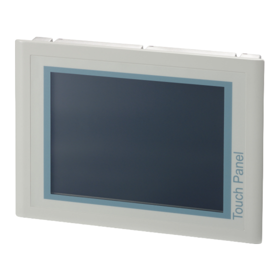
VIPA HMI Touch Panel Hardware description Properties 2.2 Properties General The VIPA Touch Panel allows you to visualize and alter operating states and recent process values of a connected PLC. The Touch Ò Panel is a compact and modular embedded PC based on Windows Ò... -
Page 10: Structure
Hardware description VIPA HMI Touch Panel Structure > Overview 2.3 Structure 2.3.1 Overview Front view 1 Slot for storage medium (CF, SD/MMC) 2 Connection for interfaces and power supply 3 Display with touch sensitive area (touch screen) Side view 1 Compact Flash 2 MMC / SD Bottom view (Inter- faces) -
Page 11: Interfaces
VIPA HMI Touch Panel Hardware description Structure > Interfaces Please make sure that the Touch Panel always has to be supplied with external voltage! 2.3.2 Interfaces RS422/485 interface 9 pin SubD jack Logical states represented by voltage differences between the 4 cores Serial bus connection in 4-wire technology using full duplex mode Data communications up to a max. - Page 12 Hardware description VIPA HMI Touch Panel Structure > Interfaces RS232 interface 9 pin SubD plug Interface is compatible to the COM interface of a PC Logical signals as voltage levels Point-to-point links with serial full-duplex transfer in two-wire tech- nology up to 15m distance Data transfer rate up to 115.2kbit/s MPI/PROFIBUS DP 9 pin SubD jack...
-
Page 13: Memory Management
VIPA HMI Touch Panel Hardware description Structure > Memory management Power supply The Touch Panel has got an integrated power supply. The power supply has to be provided with DC 24V (20.4 ... 28.8V). For this you find an according DC 24V slot on the bottom side. The power supply is protected against inverse polarity and overcur- rent. -
Page 14: Dimensions
Hardware description VIPA HMI Touch Panel Dimensions Security flap for memory cards On the left side of the Touch Panel are the card slots for memory cards. The cards are visibly covered by a security flap and are thus secured from slipping out. Please take care to pull the security flap back before plugging or pulling a memory card like shown in the illustration and put it back again afterwards. - Page 15 VIPA HMI Touch Panel Hardware description Dimensions The degrees of protection are only guaranteed when the following is observed: – Material thickness at the mounting cut-out: 1.5 ... 6mm £ – The deviation from the plane for the panel cut-out is 0.5mm.
-
Page 16: General Data
Hardware description VIPA HMI Touch Panel General data 2.5 General data Conformity and approval Conformity 2006/95/EG Low-voltage directive 2004/108/EG EMC directive Approval UL 508 Approval for USA and Canada others RoHS 2011/65/EU Product is lead-free; Restriction of the use of certain hazardous substances in electrical and electronic equipment Protection of persons and device protection... -
Page 17: Technical Data
VIPA HMI Touch Panel Hardware description Technical data > 62K-JEE0-CB Mounting conditions Mounting place In the control cabinet Mounting position Horizontal and vertical Standard Comment Emitted interfer- EN 61000-6-4 Class A (Industrial area) ence Noise immunity EN 61000-6-2 Industrial area zone B EN 61000-4-2 8kV at air discharge (degree of severity 3),... - Page 18 Hardware description VIPA HMI Touch Panel Technical data > 62K-JEE0-CB Order no. 62K-JEE0-CB Operating system Windows CE 6.0 Prof. User software Movicon 11 CE Standard Work memory 128 MB User memory 4 GB Available memory (user data) 3800 MB SD/MMC Slot ü...
- Page 19 VIPA HMI Touch Panel Hardware description Technical data > 62K-JEE0-CB Order no. 62K-JEE0-CB Audio connections Technical data power supply Power supply (rated value) DC 24 V Power supply (permitted range) DC 20.4...28.8 V Reverse polarity protection ü Current consumption (no-load operation) 0.51 A Current consumption (rated value) 0.7 A...
-
Page 20: Jee0-Cx
Hardware description VIPA HMI Touch Panel Technical data > 62K-JEE0-CX 2.6.2 62K-JEE0-CX Order no. 62K-JEE0-CX Type Touch Panel TP 610C Display Display size (diagonal) 10.4 " Display size (width) 211.2 mm Display size (height) 158.4 mm Resolution 600 x 800 / 800 x 600 Aspect ratio Type of display TFT color (64K colors) - Page 21 VIPA HMI Touch Panel Hardware description Technical data > 62K-JEE0-CX Order no. 62K-JEE0-CX COM1 connector Sub-D, 9-pin, male Serial, COM2 RS422/485 isolated COM2 connector Sub-D, 9-pin, female Number of USB-A interfaces USB-A connector USB-A (host) Number of USB-B interfaces USB-B connector USB-B (device) Number of ethernet interfaces Ethernet...
- Page 22 Hardware description VIPA HMI Touch Panel Technical data > 62K-JEE0-CX Order no. 62K-JEE0-CX Minimum 1.5 mm Maximum front panel thickness 6 mm Weight 3251 g Environmental conditions Operating temperature 0 °C to 50 °C Storage temperature -20 °C to 60 °C Certifications UL508 certification in preparation...
-
Page 23: Deployment Touch Panel
VIPA HMI Touch Panel Deployment Touch Panel Installation Deployment Touch Panel 3.1 Installation Overview The Touch Panel is suitable for the installation in operating tables and control cabinet fronts. The installation happens via the back. The Touch Panel is provided with a patented integrated fixing technique that allows an easy connection with a simple screwdriver. - Page 24 Deployment Touch Panel VIPA HMI Touch Panel Installation Connect power supply For the cabling of the DC 24V power supply green plugs with Cage- Clamp technology are deployed. The spring-clip connector tech- nology simplifies the wiring requirements for signaling and power cables.
-
Page 25: Commissioning
VIPA HMI Touch Panel Deployment Touch Panel Commissioning > VIPA Startup-Manager 3.2 Commissioning CAUTION! – Before commissioning the device must be brought to room temperature. – At condensation the device must be absolutely dry before connected to power. – To avoid overheat during operation the device must not be laid open to direct sun light. - Page 26 Deployment Touch Panel VIPA HMI Touch Panel Commissioning > VIPA Startup-Manager Administrator area With clicking on [Advanced] the administrator area is opened. On delivery there are the following buttons: KuK Tools To permanently store changes within the Registry after PowerOFF - PowerON the program KuK Tools is to be used.
- Page 27 VIPA HMI Touch Panel Deployment Touch Panel Commissioning > VIPA Startup-Manager Main Here general settings can be established. A new background picture can be loaded under "Background ...". With "Font Color" and "Back Color" the color of the button font and of the buttons can be preset.
- Page 28 Deployment Touch Panel VIPA HMI Touch Panel Commissioning > VIPA Startup-Manager Custom Here new buttons can be configured and assigned with corre- sponding programmes. Choose "Normal" for the user area or "Advanced" for the adminis- trator area. With [+] a new button can be added. Designate the button and click on [...] to assign the button to a program.
- Page 29 VIPA HMI Touch Panel Deployment Touch Panel Commissioning > VIPA Startup-Manager Copy Here with the startup of the panel files can be copied e.g. from Ò flash disk to Windows Files can be added by [+]. With [-] the corresponding file is removed from the list.
- Page 30 Deployment Touch Panel VIPA HMI Touch Panel Commissioning > VIPA Startup-Manager About Here you can find the current version of the VIPA Startup-Man- ager. Control panel To configure the COM2 interface on the Touch Panel start the tool "Com2 Configuration" via the button"Control Panel". Configuration COM2 RS422/485 In the opening dialog window you can activate the RS485 or the RS422 interface.
- Page 31 VIPA HMI Touch Panel Deployment Touch Panel Commissioning > VIPA Startup-Manager Configuration MPI/DP-Slave To configure the MPI/DP interface on the Touch Panel start via "Control Panel" the tool "MPI/DP Slave Configuration". Default: MPI - Adress 1 The following settings are only required if you not communicate via Movicon.
-
Page 32: Connection To A Plc System
Deployment Touch Panel VIPA HMI Touch Panel Operating system WindowsÒ Embedded CE 6.0 Prof. > General 3.3 Connection to a PLC system Overview For the inclusion into your PLC system several HMI/SCADA project- engineering platforms are at your disposal that has to be installed at an external PC. - Page 33 VIPA HMI Touch Panel Deployment Touch Panel Operating system WindowsÒ Embedded CE 6.0 Prof. > General Ò Ò Windows Embedded Windows Embedded CE 6.0 supports some file viewer and an CE 6.0 Internet browser. Properties ftp, http, Telnet and VNC server RAS server ActiveSync file transfer (USB, RS232) RDP (Remote Desktop Protocol)
-
Page 34: Structure
Deployment Touch Panel VIPA HMI Touch Panel Operating system WindowsÒ Embedded CE 6.0 Prof. > Structure 3.4.2 Structure Icon Via icons on the desktop you gain direct access to the application related to the icon. Ò Desktop The desktop is the screen that is shown after login to Windows CE. - Page 35 VIPA HMI Touch Panel Deployment Touch Panel Operating system WindowsÒ Embedded CE 6.0 Prof. > Structure Keyboard At pushed SHIFT key: At pushed [a´ü] key: Please note that äöü can exclusively be entered via the software keyboard "Keyboard". Large KB At pushed SHIFT key: HB160 | TP | 62K-JEE0 | GB | 14-38...
- Page 36 Deployment Touch Panel VIPA HMI Touch Panel Operating system WindowsÒ Embedded CE 6.0 Prof. > Structure Meaning Home Position 1 End End BS Backspace dn ¯ lt ¬ rt ® pgup Page pgdn Page ¯ ins Insert del Delete Tab Tabulator Shift Caps/Lock Hide keyboard...
- Page 37 VIPA HMI Touch Panel Deployment Touch Panel Operating system WindowsÒ Embedded CE 6.0 Prof. > Structure Set Ethernet parameters The dialog field for pre-setting an Ethernet address can be found in ‘Start è Settings è Network and Dial-up Connections ’. The default setting is address assignment via DHCP.
-
Page 38: Communication Via Activesync
Deployment Touch Panel VIPA HMI Touch Panel Communication via ActiveSync 3.5 Communication via ActiveSync Overview ActiveSync is a communication platform developed by Microsoft especially for mobile computers to synchronize data between a mobile device and a PC via USB. Many developer tools res. SCADA project-engineering tools use ActiveSync for the data transfer. - Page 39 VIPA HMI Touch Panel Deployment Touch Panel Communication via ActiveSync Install partnership for Now you can install a "partnership" via an USB connection with the USB communication following approach: Connect your Touch Panel via the "Device"-USB-B jack to your PC and turn on the Touch Panel. ð...
-
Page 40: Integrated Server
Deployment Touch Panel VIPA HMI Touch Panel Integrated Server > ftp server Now you can access the Touch Panel with ActiveSync via USB. To keep the settings also after power on, you have to store them to the registry with ‘START è Programs è... - Page 41 VIPA HMI Touch Panel Deployment Touch Panel Integrated Server > ftp server Conditions for ftp Depending on the ftp client your PC must have the following condi- access tions for a ftp connection. If there are still problems with the ftp access please ask your system administrator.
-
Page 42: Http Server
Deployment Touch Panel VIPA HMI Touch Panel Integrated Server > Telnet server 3.6.3 http server The Touch Panel has an integrated http server (web server) that allows depending on the access the administration of the Touch Panel res. of websites in the Touch Panel. The administrative access to the http server happens via Ethernet from the PC by setting the IP address of the Touch Panel with attached "Admin"... -
Page 43: Vnc Server
VIPA HMI Touch Panel Deployment Touch Panel Integrated Server > VNC server Enter the following: Login: wince Password: vipatp (entry is hidden) ð After entering valid user data a command line for entries appears: By entering Exit res. closing the window you may terminate the Telnet connection at any time. - Page 44 Deployment Touch Panel VIPA HMI Touch Panel Integrated Server > VNC server Because you can deactivate all safety attitudes with the VNC server, you should use these exclusively for start-up! Per default the VNC server is on delivery deactivated. Due to software reasons VIPA does not support the VNC server function! Establishing a VNC con- The VNC connection establishment has the following approach:...
-
Page 45: Access To The Network Resources
VIPA HMI Touch Panel Deployment Touch Panel Access to the network resources 3.7 Access to the network resources Overview The Touch Panel allows you to access shared resources in a Micro- soft network like drives and printer. Here you may assign existing public directories or printer in the network to local directories or printer in the Touch Panel. - Page 46 Deployment Touch Panel VIPA HMI Touch Panel Access to the network resources Configure network The configuration of a network printer happens with the following printer approach: Enter this command into the command prompt: \> net use printer name network printer Example: Printer name: Printer, network printer: \\testserver\printer Entry: \>...
-
Page 47: Firmware Update
VIPA HMI Touch Panel Deployment Touch Panel Firmware update 3.8 Firmware update Overview You can execute a firmware update via SD, CF card or USB stick. The latest firmware versions can be found in the service area under www.vipa.com. CAUTION! When installing a new firmware you have to be extremely careful. -
Page 48: Installation Guidelines
Installation Guidelines VIPA HMI Touch Panel Basic rules for the EMC-equitable assembly of installations Installation Guidelines 4.1 Basic rules for the EMC-equitable assembly of installations General The installation guidelines contain information about the interference free deployment of a PLC system. There is the description of the ways, interference may occur in your PLC, how you can make sure the electromagnetic compatibility (EMC), and how you manage the isolation. - Page 49 VIPA HMI Touch Panel Installation Guidelines Basic rules for the EMC-equitable assembly of installations Coupling mechanisms The following table shows the four different coupling mechanisms, and interference their causes and possible interference sources. sources Coupling mechanism Cause Typical source Galvanic coupling Galvanic or metallic coupling Pulsed devices (Net influ- always occurs, when two cur-...
-
Page 50: Emc-Equitable Assembly
Installation Guidelines VIPA HMI Touch Panel EMC-equitable assembly Basic rules for EMC In the most times it is enough to take care of some elementary rules to guarantee the EMC. Please regard the following basic rules when installing your PLC. Take care of a correct area-wide grounding of the inactive metal parts when installing your components. -
Page 51: Emc-Equitable Cabling
VIPA HMI Touch Panel Installation Guidelines EMC-equitable cabling Grounding means the conducting connection of all inactive metal parts. The sum of all interconnected inactive parts is called ground. Inactive parts are all conductive parts electrically separated from all active parts by means of a basic isolation and that may only get voltage in case of an error. - Page 52 Installation Guidelines VIPA HMI Touch Panel EMC-equitable cabling Group A Group B Group C Group D Group A Group B Group C Group D The lines may be installed in common bundles or cable trusses. The lines have to be installed in different bundles or cable trusses (without min.
- Page 53 VIPA HMI Touch Panel Installation Guidelines EMC-equitable cabling Equipotential bonding Potential differences can occur between different sections when con- trollers and peripheral equipment are connected by means of non-iso- lated connections or the screens of screened cables are connected at both ends and grounded on different sections of the plant.
-
Page 54: Special Precautions Providing High Noise Immunity
Installation Guidelines VIPA HMI Touch Panel Special precautions providing high noise immunity You should always use metallic or metalized covers for serial data lines. Connect the screen of the data line to the cover. Do not con- nect the screen to PIN 1 of the connector! In case of stationary opera- tions it is recommended that the remove the insulation from the screened cable without cutting the screen and to attach this point to the screening/neutral rail. - Page 55 VIPA HMI Touch Panel Installation Guidelines Special precautions providing high noise immunity Connections of DC-activated Connections of AC-activated inductors inductors using a diode using a Z-diode using a varistor using RC-net- work Power outlet for PGs Every cubicle must be provided with a power outlet for the PU. These outlets must be wired to the distribution system, which is also used to connect the neutral conductor for the cubicle.
-
Page 56: Checklist For The Emc-Compliant Installation Of Controllers
Installation Guidelines VIPA HMI Touch Panel Checklist for the EMC-compliant installation of controllers 4.5 Checklist for the EMC-compliant installation of controllers EMV-measures Space for Notes Connection of the inactive parts You should take special care to check the connections of: Module racks Frames Screen and protected earth conductor...
Need help?
Do you have a question about the VIPA 62K-JEE0 and is the answer not in the manual?
Questions and answers