
Subscribe to Our Youtube Channel
Related Manuals for YASKAWA VIPA PPC015 CE


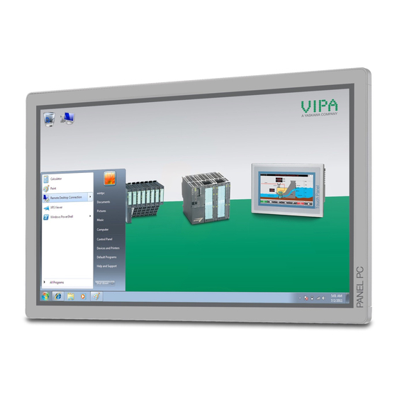
Summary of Contents for YASKAWA VIPA PPC015 CE
- Page 1 VIPA HMI PPC | 62P-PNJ0 | Manual HB160 | PPC | 62P-PNJ0 | en | 20-20 Panel PC - PPC015 CE...
- Page 2 YASKAWA Europe GmbH Ohmstraße 4 91074 Herzogenaurach Tel.: +49 9132 744 0 Fax: +49 9132 744 186 Email: info@yaskawa.eu.com Internet: www.yaskawa.eu.com 67P-PNJ0_000_PPC015CE,7,EN - © 2020...
-
Page 3: Table Of Contents
VIPA HMI Table of contents Table of contents General........................4 1.1 Copyright © YASKAWA Europe GmbH............4 1.2 About this manual..................... 5 1.3 Safety information..................... 6 Hardware description..................... 7 2.1 Safety information for users................7 2.2 Properties......................8 2.3 Structure......................9 2.3.1 Overview...................... -
Page 4: General
This material is protected by copyright laws. It may not be reproduced, distributed, or altered in any fashion by any entity (either internal or external to YASKAWA) except in accordance with applicable agreements, contracts or licensing, without the express written consent of YASKAWA and the business management owner of the material. -
Page 5: About This Manual
About this manual Document support Contact your local representative of YASKAWA Europe GmbH if you have errors or ques- tions regarding the content of this document. If such a location is not available, you can reach YASKAWA Europe GmbH via the following contact: YASKAWA Europe GmbH, Ohmstraße 4, 91074 Herzogenaurach, Germany... -
Page 6: Safety Information
VIPA HMI General Safety information CAUTION! Damages to property is likely if these warnings are not heeded. Supplementary information and useful tips. 1.3 Safety information Applications conforming The system is constructed and produced for: with specifications communication and process control general control and automation tasks industrial applications operation within the environmental conditions specified in the technical data... -
Page 7: Hardware Description
VIPA HMI Hardware description Safety information for users Hardware description 2.1 Safety information for users Handling of electrostatic VIPA-modules make use of highly integrated components in MOS-Technology. These sensitive modules components are extremely sensitive to over-voltages that can occur during electrostatic discharges. -
Page 8: Properties
VIPA HMI Hardware description Properties 2.2 Properties General The VIPA Panel PC is a combination of industrial PC with state of the art performance features and a touch panel with ideal display capabilities. The Panel PC is a compact and Ò... -
Page 9: Structure
VIPA HMI Hardware description Structure > Overview 2.3 Structure 2.3.1 Overview Front view Slot for voltage supply (DC 12-30V) VGA interface Reset button RS232/RS422/RS485 interface COM 2 RS232/RS422/RS485 interface COM 1 4x"Host"-USB-A interface RJ45 jack for Ethernet communication LAN 2 RJ45 jack for Ethernet communication LAN 1 3.5mm Audio Line out 10 Power switch (pushbutton) - Page 10 VIPA HMI Hardware description Structure > Overview Bottom view Slot for voltage supply (DC 12-30V) VGA interface Reset button RS232/RS422/RS485 interface COM 2 RS232/RS422/RS485 interface COM 1 4x"Host"-USB-A interface RJ45 jack for Ethernet communication LAN 2 RJ45 jack for Ethernet communication LAN 1 3.5mm Audio Line out Please make sure that the Panel PC always has to be supplied with external voltage!
-
Page 11: Interfaces
VIPA HMI Hardware description Structure > Interfaces 2.3.2 Interfaces HB160 | PPC | 62P-PNJ0 | en | 20-20... - Page 12 VIPA HMI Hardware description Structure > Interfaces RS232/RS422/RS485 inter- The 9-pin male SubD connector may be switched with BIOS. Here also the termination face (switchable) resistor of the RS422 and RS485 interface may be activated or deactivated. Ä ‘Submenu "Serial Port 1 Configuration"’ page 41 RS232 interface Logical conditions as voltage level Point-to-point connection with serial full-duplex transfer...
- Page 13 VIPA HMI Hardware description Structure > Interfaces HB160 | PPC | 62P-PNJ0 | en | 20-20...
-
Page 14: Memory Management
VIPA HMI Hardware description Structure > Memory management VGA interface VGA SubD HD15 jack to connect a second display. Line out 3.5 mm stereo jack to connect an active speaker system or an earphone. "Host"-USB-A Using the "Host"-USB-A interface USB mouse, keyboard, stick or USB hard discs can be connected. - Page 15 VIPA HMI Hardware description Structure > Memory management Assignment Assignment n.c. SATA_TX1+ SATA_TX1- CFAST_LED1_C CFAST_LED2_C SATA_RX1+ PC10 n.c. SATA_RX1- PC11 n.c. PC12 n.c. CFAST_CDI PC13 VCC3 PC14 VCC3 n.c. PC15 n.c. PC16 n.c. PC17 CFAST_CDO Prior to removing the CFast card, make sure the unit's power is off and disconnected from the power supply.
-
Page 16: Dimensions
VIPA HMI Hardware description Dimensions 2.4 Dimensions Installation dimensions For the installation of the Panel PC in control cabinets and desks the following dimen- sions are necessary: 15.6" - 67P-PNJ0-... Front panel thickness 3 ... 12mm Installation cutting (W x H) 401 x 296mm Front panel (W x H x T) 417.8 x 312.8 x 6.2mm... -
Page 17: General Data
VIPA HMI Hardware description General data 2.5 General data Conformity and approval Conformity 2014/35/EU Low-voltage directive 2014/30/EU EMC directive Approval Refer to Technical Data others RoHS 2011/65/EU Restriction of the use of certain hazardous substances in electrical and electronic equipment Protection of persons and device protection Type of protection IP20... -
Page 18: Technical Data
VIPA HMI Hardware description Technical data Standard Comment Emitted interference EN 61000-6-4 Class A (Industrial area) Noise immunity EN 61000-6-2 Industrial area zone B EN 61000-4-2 8kV at air discharge (degree of severity 3), 4kV at contact discharge (degree of severity 2) EN 61000-4-3 HF field immunity (casing) 80MHz …... - Page 19 VIPA HMI Hardware description Technical data Order no. 67P-PNJ0-EB CFast Slot ü Time Real-time clock buffered ü Clock buffered period (min.) Type of buffering lithium battery Load time for 50% buffering period Load time for 100% buffering period Accuracy (max. deviation per day) 10 s Operating controls Touchscreen...
- Page 20 VIPA HMI Hardware description Technical data Order no. 67P-PNJ0-EB Inrush current 1.3 A I²t 0.35 A²s Power loss 32 W Status information, alarms, diagnostics Supply voltage display none Mechanical data Housing / Protection class Material coated aluminium steel plate Mounting via integrated pivoted lever Protection class IP front side IP 65...
-
Page 21: Deployment Panel Pc
VIPA HMI Deployment Panel PC Installation Deployment Panel PC 3.1 Installation Overview The Panel PC is suitable for the installation in operating tables and control cabinet fronts. The installation happens via the back. The Panel PC is provided with a fixing technique with not losable screws that allows an easy connection with a crosstip screwdriver. -
Page 22: Installation Of The Cfast Card
VIPA HMI Deployment Panel PC Installation of the CFast card Connect power supply For the cabling of the power supply DC 12-30V a green plug is used. The connector is a plug with screw contacts. The plug has the following assignment: DC 24V DC 0V PE Protective earth... -
Page 23: Commissioning
VIPA HMI Deployment Panel PC Commissioning > Startup-Manager 3.3 Commissioning CAUTION! – Before commissioning the device must be brought to room tempera- ture. – At condensation the device must be absolutely dry before connected to power. – To avoid overheat during operation the device must not be laid open to direct sun light. - Page 24 VIPA HMI Deployment Panel PC Commissioning > Startup-Manager There is a button on the initial screen with a counter, which counts backwards. If you click on this button within this time, the project will start. If the time expires, the project will start automatically.
- Page 25 VIPA HMI Deployment Panel PC Commissioning > Startup-Manager With [...] at ‘ Runtime path’ res. ‘Project path’ all existing runtimes res. projects on the panel and the storage media will be listed. Under ‘Delay Time’ you can adjust a delay time > 0 by using the buttons [+] and [-]. 5 seconds are default.
-
Page 26: Connection To A Plc System
VIPA HMI Deployment Panel PC Connection to a PLC system 3.4 Connection to a PLC system Overview For the inclusion into your PLC system several HMI/SCADA project-engineering plat- forms are at your disposal that has to be installed on an external PC. Here you can create your project, where appropriate simulate it and transfer it to the Panel PC via a connection that you’ve entered before. -
Page 27: Operating System Windows Embedded Compact 7
VIPA HMI Deployment Panel PC Operating system Windows Embedded Compact 7 > General 3.5 Operating system Windows Embedded Compact 7 3.5.1 General Ò Windows Embedded Compact 7 - WEC7 is the next generation of Windows CE oper- ating systems designed for innovative and small-footprint devices. Features File viewer for Word, Excel, PowerPoint and PDF ftp, Telnet and VNC server... -
Page 28: Structure
VIPA HMI Deployment Panel PC Operating system Windows Embedded Compact 7 > Structure 3.5.2 Structure Icon Via icons on the desktop you gain direct access to the application related to the icon. Ò Desktop The desktop is the screen that is shown after login to Windows . - Page 29 VIPA HMI Deployment Panel PC Operating system Windows Embedded Compact 7 > Structure Show desktop All windows are minimized and the desktop is shown. Software keyboard This button displays a keyboard at the screen. "Hide Input Panel" hides the key- board again.
-
Page 30: Integrated Server
VIPA HMI Deployment Panel PC Integrated server > General Set Display Via ‘Start è Settings è Control Panel è Display’ the dialog windows for the display properties opens. Here you can change the settings for the monitor options. Set Ethernet Parameters The dialog field for pre-setting an Ethernet address can be found in ‘Start è... -
Page 31: Ftp Server
VIPA HMI Deployment Panel PC Integrated server > ftp server Data transfer Client ® Server Upload 3.6.2 ftp server By means of a ftp server data between client and server can be exchanged. Here you can copy, delete or create files and directories. Conditions for ftp access Depending on the ftp client your PC must have the following conditions for a ftp connec- tion. -
Page 32: Telnet Server
VIPA HMI Deployment Panel PC Integrated server > Telnet server 3.6.3 Telnet server Telnet is a text based client-server protocol on TCP level. Using of a Telnet client like e.g. Ò the "MS-DOS console" in your Windows operating system you may execute text based all file remote functions at your Panel PC like copy, delete and create files and directories. -
Page 33: Vnc Server
Because you can deactivate all safety attitudes with the VNC server, you should use these exclusively for start-up! For this reason the VNC server is on delivery deactivated. Due to software reasons YASKAWA does not support the VNC server function! Establishing a VNC con-... - Page 34 VIPA HMI Deployment Panel PC Integrated server > VNC server Click on [Options] and deactivate the field "Emulate 3 Buttons..." like shown at Mouse. Enter the IP address of the Panel PC at VNC server. Click on [OK] and enter the password vipatp.
-
Page 35: Access To The Network Resources
VIPA HMI Deployment Panel PC Access to the network resources 3.7 Access to the network resources Overview The Panel PC allows you to access shared resources in a Microsoft network like drives and printer. Here you may assign existing public directories or printer in the network to local directories or printer in the Panel PC. -
Page 36: Bios Setup
VIPA HMI BIOS setup Overview BIOS setup 4.1 Overview In this chapter you will find information, required for calling the BIOS setup and the possible settings. The BIOS (Basic Input and Output System) setup program is a menu driven utility that enables you to make changes to the system configuration and tailor your system to suit your individual work needs. -
Page 37: Main
VIPA HMI BIOS setup Main Legends Function ßà Moves the highlight left or right to select a menu áâ Moves the highlight up or down between submenus or fields Exits the BIOS setup utility Scrolls forward or backward through the values or options of the highlighted field Tabulator Selects a field... -
Page 38: Advanced
VIPA HMI BIOS setup Advanced Intel RC Version Display the Intel Reference Code version. System Date The date format is day month/date/year an. Day displays a day, from Monday to Sunday. Month displays the month, from January to December. Date displays the date, from 1 to 31. Year displays the year, from 1999 to 2099. - Page 39 VIPA HMI BIOS setup Advanced Submenu "CPU Configura- This section is used to configure the CPU. tion" Hyper-Threading This field is used to enable or disable hyper-threading. Execute Disable Bit XD can prevent certain classes of malicious buffer overflow attacks. Enabled - Permit the switching on of the execute disable function by the OS.
- Page 40 VIPA HMI BIOS setup Advanced SATA Controller(s) Enables or disables SATA controller. Configure SATA as Configures the SATA as IDE or AHCI mode. - This option configures the serial ATA drives as parallel ATA physical storage device. AHCI - This option configures the serial ATA drives to use AHCI (AdvancedHost Con- troller Interface).
- Page 41 VIPA HMI BIOS setup Advanced Legacy USB Support Due to the limited space of the BIOS ROM, the support for legacy USB keyboard (in DOS mode) is by default set to disabled. With more BIOS ROM space available, it will be able to support more advanced features as well as provide compatibility to a wide variety of peripheral devices.
- Page 42 VIPA HMI BIOS setup Advanced Serial Port Enables or disables the serial port. Disabled - Serial port is not available Enabled - (default) Serial port is available Change Settings Selects an optimal setting for the super IO device. Onboard Serial Port 1 This field is used to configure the mode of serial port 1 as RS232, RS422 (default), Mode RS485 or RS485 AUTO.
-
Page 43: Chipset
VIPA HMI BIOS setup Chipset 4.4 Chipset This section is used to configure the system based on the specific features of the chipset. CAUTION! Setting incorrect field values may cause the system to malfunction. Host Bridge Display the memory information. Ò... - Page 44 VIPA HMI BIOS setup Chipset IGFX-Boot Type This field is used to configure which video device will be activated during POST. This has no effect if external graphics present. The options are CRT, LVDS, DP-LVDS + CRT. Backlight Control Select The available options are ‘Pyroelectric sensor’...
- Page 45 VIPA HMI BIOS setup Chipset Backlight Adjust the brightness of the backlight. Fixed Graphics Memory This field is used to configure the memory size of the fixed graphics, the options are Size 128MB and 256MB. Submenu "South Bridge" This field is used to configure the south bridge chipset. Azalia Controller This section disables Azalia or enables HD Audio.
-
Page 46: Boot
VIPA HMI BIOS setup Boot 4.5 Boot This section is used to configure the boot features. Setup Promt Timeout This section configures the number of seconds to wait for the setup activation key. Bootup NumLock State This allows you to determine the default state of the numeric keypad. On - (default) The function of the numeric keypad is the number keys. -
Page 47: Security
VIPA HMI BIOS setup Security 4.6 Security If ONLY the Administra- If only the Administrator's password is set, then this only limits access to setup and is only tor's password is set asked for when entering setup. If ONLY the User's pass- If only the User's password is set, then this is a power on password and must be entered word is set to boot or enter setup. -
Page 48: Save And Exit
VIPA HMI BIOS setup Save and exit 4.7 Save and exit Save Changes and Exit To save the changes and exit the setup utility, select this field then press [Enter]. A dialog box will appear. Confirm by selecting [Yes]. You can also press [F4] to save and exit setup. Discard Changes and Exit To exit the Setup utility without saving the changes, select this field then press [Enter]. - Page 49 VIPA HMI BIOS setup Save and exit Save as User Defaults To use the current configurations as user default settings for the BIOS, select this field then press [Enter]. A dialog box will appear. Confirm by selecting [Yes]. Restore User Defaults To restore the BIOS to user default settings, select this field then press [Enter].
-
Page 50: Installation Guidelines
VIPA HMI Installation guidelines Basic rules for the EMC-equitable assembly of installations Installation guidelines 5.1 Basic rules for the EMC-equitable assembly of installations General The installation guidelines contain information about the interference free deployment of a PLC system. There is the description of the ways, interference may occur in your PLC, how you can make sure the electromagnetic compatibility (EMC), and how you manage the isolation. - Page 51 VIPA HMI Installation guidelines Basic rules for the EMC-equitable assembly of installations Coupling mechanism Cause Typical source Capacitate coupling Capacitate or electric coupling occurs Interference through parallel signal between conductors with different lines potential. The coupling is propor- Static discharge of the personnel tionate to the temporal change of the Contactors voltage.
- Page 52 VIPA HMI Installation guidelines Basic rules for the EMC-equitable assembly of installations Proof the correct fixing of the lead isolation. – Data lines must be laid isolated. – Analog lines must be laid isolated. When transmitting signals with small ampli- tudes the one sided laying of the isolation may be favourable.
-
Page 53: Emc-Equitable Assembly
VIPA HMI Installation guidelines EMC-equitable assembly 5.2 EMC-equitable assembly Mostly, measures for suppressing interference voltages are only taken, when the control is already in commission and the perfect receive of a wanted signal is disturbed. Causes for such interference's are in the most cases inadequate reference potentials, coming from mistakes at the device assembly and installation. -
Page 54: Emc-Equitable Cabling
VIPA HMI Installation guidelines EMC-equitable cabling 5.3 EMC-equitable cabling Line routing Content of this section is the line routing of bus, signal and supply lines. Object of the line routing is to suppress the "slurring" at parallel lines. Line routing inside and For an EMC-equitable routing of the lines it is convenient to divide the cables in different outside of cubicles groups and install each group itself:... - Page 55 Install these protective elements at the location where the cables enter the building. Any lightning protection system must be based on an individual assess- ment of the entire plant. For questions please contact YASKAWA Europe GmbH. Equipotential bonding Potential differences can occur between different sections when controllers and periph-...
- Page 56 VIPA HMI Installation guidelines EMC-equitable cabling Avoid cables with foil-type screens as the foil can be easily damaged by tension and pressure at the point of attachment; this can result in reduced effectiveness of the screening action. As a rule you should always ground the screens of cables on both ends. This is the only way in which you can ensure that high frequency interference is attenuated prop- erly.
-
Page 57: Special Precautions Providing High Noise Immunity
VIPA HMI Installation guidelines Special precautions providing high noise immunity 5.4 Special precautions providing high noise immunity Inductors require snubber Inductors controlled by your programmable controller (e.g. contactors and relays) do not networks normally require additional snubber networks or suppressors as the respective modules have been provided with the required components. -
Page 58: Checklist For The Emc-Compliant Installation Of Controllers
VIPA HMI Installation guidelines Checklist for the EMC-compliant installation of controllers 5.5 Checklist for the EMC-compliant installation of controllers EMC-measures Space for Notes Connection of the inactive parts You should take special care to check the connections of: Module racks Frames Screen and protected earth conductor Are all the inactive metal parts interconnected by means of large-surface and low-...
Need help?
Do you have a question about the VIPA PPC015 CE and is the answer not in the manual?
Questions and answers