Banner R95C Instruction Manual
8-port 2-channel discrete io-link hub
Hide thumbs
Also See for R95C:
- Instruction manual (5 pages) ,
- Manual (6 pages) ,
- Instruction manual (25 pages)
Table of Contents
Advertisement
Quick Links
R95C 8-Port 2-Channel Discrete IO-Link Hub Instruction Manual
Features
Models
Housing
R95
Overview
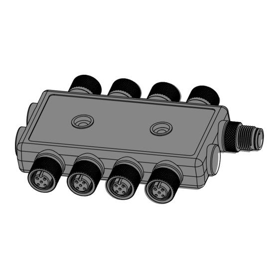
The R95C-8B22-KQ hub connects two discrete Input/Output channels to each of the eight unique ports, providing access to monitoring and configuring those ports
with an IO-Link master. Host mirroring is available where a selected port input/output discrete signal can be routed to Pin 2 (male) on the PLC/Host connection.
Configuration
Figure 1 details the logic flow for each of the eight ports, while the tables define the configuration for each pin.
For more information, see P/N 233583 R95C-8B22-KQ IO-Link Data Reference Guide and P/N 233584 R95C-8B22-KQ IODD Files.
Input State
B
E
C
.
ANNER
NGINEERING
ORP
•
Compact bimodal to IO-Link device converter that connects discrete inputs and sends the
value to the IO-Link Master
•
Outputs a discrete value as received from IO-Link Master Process Data Out
•
Enabled Delay Modes: ON/OFF Delay, ON/OFF One-shot, ON/OFF/Retriggerable One-shot,
ON/OFF Pulse-stretcher and Totalizer
•
Measurement Metrics: Count, Events Per Minute (EPM), and Duration
•
Discrete Mirroring: Discrete signals (In/Out) from all eight ports can be mirrored to any of the
eight ports, Discrete Out, or the host white wire output
•
Discrete input/output can be independently configured as NPN or PNP
•
Rugged overmolded design meets IP65, IP67, and IP68
•
Connects directly to a sensor or anywhere in-line for ease of use
•
R95C IO-Link hubs are a quick, easy, and economical way to integrate non-IO-Link devices
into an IO-Link system
Function
Converter
C
8B22
C = Converter
8B22 = 8-port,
bimodal, 2
inputs, 2 outputs
Delay Mode
• Disabled
• On/Off Delay
Discrete 1 & 2
• On/Off/Retriggerable One-shot
Selection
• On/Off Pulse Stretcher
• Totalizer
Ouput
Mirroring
Enable
Disabled
Host
Enabled
Mirroring
Enable
Figure 1: Logic Flow
March 13, 2023
Control
Connector
K
K = IO-Link
Q = M12 integral
quick disconnect
Measurement Statistics
Measurement
• Count
Statistics
• RPM
• Duration
Process Data In
Input
Process Data
• Discrete 1 and 2 Input State (active/inactive)
Input
Process Data Out
Process Data
• Discrete 1 and 2 Output State (active/inactive)
Input
Enabled
Mirroring - Discrete 1 and 2 Output
Mirroring
• Port/Channel selected state driven to Pin 2 (F) and Pin 4 (F)
Process Data
Process Data Out - Discrete 1 and 2 Output
Output
• Process Data Out selected state driven to Pin 2 (F) and Pin 4 (F)
Host Mirroring
Host Mirroring - Discrete Host Out
• Port/Channel selected state driven to Pin 2 (M)
Q
Advertisement
Table of Contents

Subscribe to Our Youtube Channel
Related Manuals for Banner R95C


Summary of Contents for Banner R95C
- Page 1 Overview The R95C-8B22-KQ hub connects two discrete Input/Output channels to each of the eight unique ports, providing access to monitoring and configuring those ports with an IO-Link master. Host mirroring is available where a selected port input/output discrete signal can be routed to Pin 2 (male) on the PLC/Host connection.
- Page 2 Pin 4 – Discrete 1 Host Mirroring Channel Selection • Pin 2 – Discrete 2 • Not Inverted Host Mirroring Inversion • Inverted • Host Mirroring Polarity • • Open Collector Host Mirroring Output Type • Push/Pull © Banner Engineering Corp. www.bannerengineering.com...
- Page 3 Mechanical Installation Install the R95C to allow access for functional checks, maintenance, and service or replacement. Do not install the R95C in such a way to allow for intentional defeat. Fasteners must be of sufficient strength to guard against breakage. The use of permanent fasteners or locking hardware is recommended to prevent the loosening or displacement of the device.
- Page 4 Overcurrent protection may be provided with external fusing or via Current Limiting, Class 2 Power Supply. Supply wiring leads < 24 AWG shall not be spliced. For additional product support, go to www.bannerengineering.com. Supply Wiring (AWG) Required Overcurrent Protection (A) Supply Wiring (AWG) Required Overcurrent Protection (A) © Banner Engineering Corp. www.bannerengineering.com...
- Page 5 Cet appareil est conforme à la norme NMB-3(B). Le fonctionnement est soumis aux deux conditions suivantes : (1) ce dispositif ne peut pas occasionner d'inter- férences, et (2) il doit tolérer toute interférence, y compris celles susceptibles de provoquer un fonctionnement non souhaité du dispositif. Dimensions All measurements are listed in millimeters [inches], unless noted otherwise. © Banner Engineering Corp. www.bannerengineering.com...
- Page 6 Engineering Corp. will repair or replace, free of charge, any product of its manufacture which, at the time it is returned to the factory, is found to have been defective during the warranty period. This warranty does not cover damage or liability for misuse, abuse, or the improper application or installation of the Banner product.
Need help?
Do you have a question about the R95C and is the answer not in the manual?
Questions and answers