Table of Contents
Advertisement
Quick Links
USER GUIDE
When replacing any part on this appliance, use only spare parts that you can be assured conform to the safety and performance
specification that we require. Do not use reconditioned or copy parts that have not been clearly authorised by Ideal Heating.
For the very latest copy of literature for specification and maintenance practices visit our website idealheating.com
where you can download the relevant information in PDF format.
August 2021
UIN 223441 A04
LOGIC MAX SYSTEM S
15IE 18IE 24IE 30IE
Advertisement
Table of Contents

Related Manuals for Ideal Heating LOGIC MAX SYSTEM S 18IE


Summary of Contents for Ideal Heating LOGIC MAX SYSTEM S 18IE
- Page 1 When replacing any part on this appliance, use only spare parts that you can be assured conform to the safety and performance specification that we require. Do not use reconditioned or copy parts that have not been clearly authorised by Ideal Heating.
- Page 2 Benchmark Commissioning Checklist. You can check your installer by calling Gas Safe Register direct on 0800 4085500. Ideal Heating is a member of the Benchmark scheme and fully supports the aims of the programme. Benchmark has been introduced to improve the standards of installation and commissioning of central heating systems in the UK and to encourage the regular servicing of all central heating systems to ensure safety and efficiency.
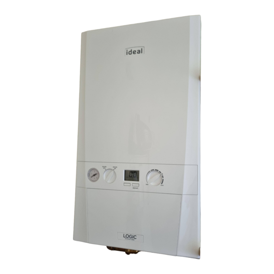
- Page 3 BOILER OPERATION Legend A. CH temperature control B. Mode Control Knob C. Boiler Status BOILER BOILER D. Burner ‘on’ indicator E. Function Button ºC F. Restart Button G. Pressure Gauge H. Central Heating Economy Setting RESTART TO START THE BOILER EFFICIENT HEATING SYSTEM OPERATION If a programmer is fitted refer to separate instructions for the The boiler is a high efficiency, condensing appliance which will...
- Page 4 CONDENSATE DRAIN GENERAL INFORMATION This appliance is fitted with a siphonic condensate trap system BOILER PUMP that reduces the risk of the appliance condensate from freezing. The boiler pump will operate briefly as a self-check once every 24 However should the condensate pipe to this appliance freeze, hours, regardless of system demand.
- Page 5 POINTS FOR THE BOILER USER Note. In line with our current warranty policy we would ask that you check through the following guide to identify any problems external to the boiler prior to requesting a service engineers visit. Should the problem be found to be other than with the appliance we reserve the right to levy a charge for the visit, or for any pre-arranged visit where access is not gained by the engineer.
- Page 6 NORMAL OPERATION DISPLAY CODES DESCRIPTION DISPLAY CODE ON BOILER The boiler is in standby operation awaiting either a central heating call or hot water demand. The boiler has a call for central heating but the appliance has reached the desired temperature set on the boiler.
- Page 7 FAULT CODES DESCRIPTION ACTION DISPLAY CODE ON BOILER No Water Flow Please contact Ideal (if under warranty) or alternatively a Gas Safe Registered Engineer if outside of the warranty period. In IE contact a Registered Gas Installer (RGII). 1. Check other gas appliances in the house are working to confirm a supply is present in Flame Loss the property.
Need help?
Do you have a question about the LOGIC MAX SYSTEM S 18IE and is the answer not in the manual?
Questions and answers