
Related Manuals for YOKOGAWA DO70G


Summary of Contents for YOKOGAWA DO70G
- Page 1 User’s Manual Model DO70G Optical Dissolved Oxygen Sensor IM 12J05D04-01E IM 12J05D04-01E 8th Edition...
-
Page 2: Introduction
Confirming the Specifications The DO70G sensor cable should have the specified length. The crimp-on terminals are either pin-type or M4 ring-type. Upon arrival of the purchased product, carefully unpack it and make sure the product has not been damaged during transportation. -
Page 3: Safety Precautions
• No part of the user’s manuals may be transferred or reproduced without prior written consent from YOKOGAWA. • YOKOGAWA reserves the right to make improvements in the user’s manuals and product at any time, without notice or obligation. • If you have any questions, or you find mistakes or omissions in the user’s manuals, please contact our sales representative or your local distributor. -
Page 4: After-Sales Warranty
Yokogawa does not warrant conformance with the specific application at the user site. Yokogawa will not bear direct/indirect responsibility for damage due to a specific application. l Yokogawa will not bear responsibility when user configures the product into systems or resells the product. - Page 5 Blank Page...
-
Page 6: Table Of Contents
<CONTENTS> Model DO70G Optical Dissolved Oxygen Sensor IM 12J05D04-01E 8th Edition CONTENTS Introduction ....................i Safety Precautions ..................ii After-sales Warranty ...................iii General ...................... 1-1 Features ......................1-1 1.2 Components ...................... 1-1 1.3 Standard Specifications ................... 1-2 1.4 Model and Suffix Codes ................... 1-3 1.5 External View and Dimensions ................ 1-4 Installing the Sensor and Connecting the Cable ........2-1 Preparing for Installation ................. - Page 7 Blank Page...
-
Page 8: General
<1. General> General Do not drop the sensor. Please handle it with care. Features • Long stability The sensor will be ready for measurement approximately 10 minutes after turning on the power. The sensor can be used continuously and stably for a long time thanks to the stain-resistant sensor cap and the measurement method which is less susceptible to disturbance. - Page 9 Use a power supply with an output voltage in the range of 24 V DC ± 10% and power consumption of 1 W or higher. • For wiring the DO70G, connect the input and output cables of the 24 V power supply by separating them by a minimum spatial distance of 3 mm and creepage distance of 6 mm.
- Page 10 When ordering DO70G with the holder, refer to the combination table below and select an adaptor according to the Holder Option Code. If you order only DO70G, please make a separate order for the adaptor by Part No. in the table below. However, if you are already using DOX8HS/PB350G/PB360G and DO70G, you can use the existing adaptor.
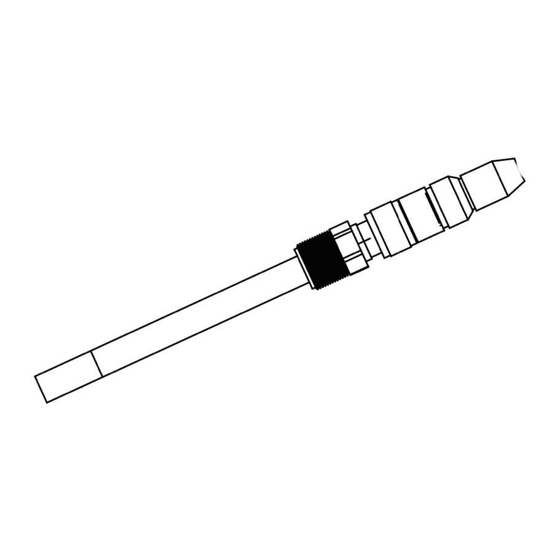
- Page 11 <1. General> 1.5 External View and Dimensions DO70G Sensor No cable type Unit: mm Variopin connector Approx. Approx. 54 119.75±1 Cable length (code): -03E, -05E, -10E Approx. 70 Approx. 90 1500 L (3 m, 5 m, 10 m) Cable length (code): -05D, -10D, -15D, -20D Approx.
-
Page 12: Installing The Sensor And Connecting The Cable
<2. Installing the Sensor and Connecting the Cable>> Installing the Sensor and Connecting the Cable Preparing for Installation Protection caps are mounted at both ends of the D70G to prevent the sensor cap or sensor plugs from being damaged. When installing the sensor, remove these protection caps. n Attaching/Detaching the sensor cable Attachment ●... -
Page 13: Selecting The Measurement Point
Assembling the Adaptor Installation The DO70G optical dissolved oxygen sensor can be assembled into the PB350G angled floating ball holder, PB360G vertical floating ball holder, or DOX8HS submersion type holder. The assembly is submerged to the optimum point to obtain precise measurements. -
Page 14: Selecting The Sensor Holder
<2. Installing the Sensor and Connecting the Cable>> 2.2.2 Selecting the Sensor Holder Each holder or fitting where the DO70G Optical Dissolved Oxygen Sensor is assembled has the following characteristics. Choose a holder that suits the liquid to be measured and the measurement location. -
Page 15: Installing The Sensor In The Holder
2.3 Connecting the Sensor Cable Sensor cable to connect to DO70G is defined by the model of converter to be used. For information on sensor cable to connect DO70G to DO402G, refer to the user’s manual for DO402G Dissolved Oxygen Converter instruction manual (IM 12J05D02-01E) or the one for DOX10 (IM 12J05S01-01E). - Page 16 Setting and Calibrating the Converter See the DO402G Dissolved Oxygen Converter user’s manual (IM 12J05D02-01E). For information on sensor cable to connect DO70G to DO402G, refer to the user’s manual IM 12J05D02-01E for DO402G Dissolved Oxygen Converter instruction manual and IM 12J05S01- 01E for DOX10.
- Page 17 Blank Page...
-
Page 18: Routine Inspection
Replace the sensor cap and the attached O-ring together with new ones. Replace DO70G sensor unit with a new one if resistance temperature detector (RTD) fails or the error still occurs even after the procedure 1 or 2 above is applied. -
Page 19: Maintenance Parts
<4. Maintenance> Maintenance Parts Part Name Part No. Remarks Sensor cap (O-ring is Please shade the light during safe keeping. attached) K9679AN The recommendable exchange cycle of a sensor cap is 1 time in 6 to 12 months. Zero adjusting reagent Sodium sulfite(Na ) 500 g Calibration must be carried out at a predetermined... - Page 20 Title : Model DO70G Optical Dissolved Oxygen Sensor Manual No. : IM 12J05D04-01E July 2023/8th Edition Deletion of DO70G Option Codes, etc. (pages 1-3, 2-3) Feb. 2023/7th Edition Deleted DOX8W (P. 1-3) Jan. 2020/6th Edition Changed Style of DOX8W [Style: S2] (thermometer was removed) (P. 1-3) Dec. 2018/5th Edition...
- Page 21 Blank Page...
Need help?
Do you have a question about the DO70G and is the answer not in the manual?
Questions and answers