
Subscribe to Our Youtube Channel
Related Manuals for YOKOGAWA DO71


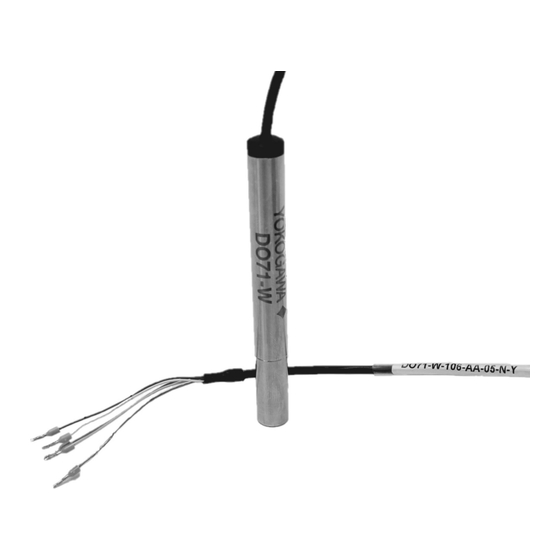
Summary of Contents for YOKOGAWA DO71
- Page 1 Instruction Model DO71 Optical Dissolved Oxygen Sensor Manual IM12J06J01-00EN-P edition...
- Page 2 If any protection or safety circuit is required for the system controlled by the product or for the product itself, prepare it separately. • Be sure to use the spare parts approved by Yokogawa Process Analyzers Europe B.V. (hereafter simply referred to as YOKOGAWA) when replacing parts or consumables.
- Page 3 No part of the Instruction manuals may be transferred or reproduced with out prior written consent from YOKOGAWA. • YOKOGAWA reserves the right to make improvements in the Instruction manuals and product at any time, without notice or obligation. •...
-
Page 4: Table Of Contents
3.6 Installation procedure for the sensor to DOX8HS ....12 3.7 Mounting sensor using adapters ...........12 4. DIMENSIONS .................15 5. WIRING ..................16 5.1 DO71 optical DO sensor grounding ........17 6. GENERAL CALIBRATION & MAINTENANCE PROCEDURE ..18 6.1 Pre-Calibration Input ..............18 6.2 DO71 two-point (Re)calibration ..........18 6.3 Maintenance of the DO71 sensor ..........20... -
Page 5: Preface
• Model Code and Serial Number. the digitization of the future. • Original Purchase Order and Date. The DO71 sensor is ideally suited for ap- • Length of time in service and descrip- plications in W&WW where it must stand tion of the process. -
Page 6: Serial Number
1.4 Serial number The Serial number is defined by nine (9) alphanu- meric characters: Production location Year/Month code Tracking number Example: N3X380005 Table 1: Production Year code Table 2: Production Month code Year Year code Year Year code Month Month code 2014 2026 January 2015 2027 February 2016 2028 March 2017... -
Page 7: General Specifications
2. GENERAL SPECIFICATIONS 2.1 Measuring elements Optical dissolved oxygen sensor in probe body and an oxygen exchange cap (OEC). 2.2 Electrical specifications Output signal: Bi-directional digital communication Physical layer: RS485 Protocol: MODBUS, RTU mode Data rate: Default 19200 b/s (8, No Parity, 2 stop bits) Power supply: +7 …... -
Page 8: Shipping Details
Approx. 360x220x105 mm (14.2x8.7x4.1 inch) Package weight (max.) Sensor cable length Sensor and cable weight Total package weight DO71 3m (9.84 ft) 100.4 (0.22) g (lbs) 260 (0.57) g (lbs) DO71 5m (16.40 ft) 138 (0.30) g (lbs) 297 (0.65) g (lbs) DO71 10m (32.80 ft) -
Page 9: Regulatory Compliance
2.7 Regulatory compliance Directive: 768/2008/EC CE-mark has been affixed on the product in 2021 for the First time UKCA UKCA-mark has been affixed on the product in 2021 for the first time. Directive: 2014/30/EU Standards: EN 61326-1:2013; IEC 61326-1:2012 Table 2 (for use in industrial locations) EN 55011:2016/A1:2017; CISPR11: 2015/ A1:2016 Group 1, Class B (for use in domestic estab lishments) Approvals ACMA... -
Page 10: Installation Of Do71
3. INSTALLATION OF DO71 Using the sensor adapters the DO71 optical dissolved oxygen sensor can be assembled into the complete Yokogawa flow and immersion fitting program: Flow fitting FF20, FF40, PB350G/PB30 an- gled floating ball holder, PB360G vertical floating ball holder, or DOX8HS submer- sion type holder. Flow and immersion fitting program allows sensor to be immersed or submerged to the optimum point to obtain precise measurements. -
Page 11: Installation Procedure For The Sensor To Pb350G/Pb360G
3.5 Installation procedure for the sen- sor to PB350G/PB360G 1. Pass GLAND from the cable side and place the bottom of the sensor on GLAND as shown in the posture of the Adapter Fig. 5. 2. Remove the protective cover put on the head of the sensor (Fig. -
Page 12: Installation Procedure For The Sensor To Dox8Hs
ADAPTER is less than 87mm. Fig. 10: Sensor positioning 3.7 Mounting sensor using adapters To mount the DO71 into various process connection use adapters set K1531JA as described in figure 11 and figure 12. IM12J06J01-00EN-P... - Page 13 Adapter set K1531JA Adapter K1520JN / K1500DV / K1520JP Figure 11. DO71 installation in Yokogawa FF20 fitting using the adapter K1531JA sensor adapter set and adapter to fitting K1520JN, K1500DV or K1520JP IM12J06J01-00EN-P...
- Page 14 Adapter set K1531JA PG13.5 adapter K1523JA (Noryl) K1523JC (SS) Figure 12. DO71 installation in Yokogawa FF40 fitting using the adapter K1531JA sensor adapter set to fit in PG13.5 fitting adapter K1523JA (Noryl) K1523JC (SS) IM12J06J01-00EN-P...
-
Page 15: Dimensions
4. DIMENSIONS The DO71 sensor is provided with in four cable lengths as described in table 3. Sensor and O-ring dimensions are described in Fig. 13. Table 3: Sensor model code and cable length Model code L (mm) L (ft) -
Page 16: Wiring
(0.14mm2) cable, stripped wire end (5 mm) for terminal connection (Fig. 14) as described in table 4. For information on DO71 sensor cable connection to FLXA402, refer to the Instruc- tion manual for FLXA402 4-Wire Converter (IM12A01F01-02EN). Fig. 14. D6 module terminal assignment for DO71 dissolved oxygen sensor... -
Page 17: Do71 Optical Do Sensor Grounding
The DO71 dissolved oxygen optical sen- sor housing is made of stainless steel with high corrosion resistance (SUS 316 L). However, electric potential differ- ences between the DO71 and a tank or other peripherals in the tank can cause immediate corrosion through electrol- ysis. Therefore, please ensure to avoid... -
Page 18: General Calibration & Maintenance Procedure
Then follow the instructions in analyzer calibration setting chapter 6.2 DO71 two-point (Re)calibration respectively. In case of requirement for recalibration of DO71 use Two-point calibration in oxy- After recording the first calibration point gen free environment (e. g. nitrogen 5.0, remove the calibration solution cal 0, fill 1 % sodium sulfite solution) and a sec- the vessel with distilled water and stir it ond calibration medium between 1 and for 1 minute. - Page 19 Fig. 17: Example of Final inspection protocol IM12J06J01-00EN-P...
-
Page 20: Maintenance Of The Do71 Sensor
6.3 Maintenance of the DO71 sensor 6.3.1 Routine inspection Cleaning of Oxygen Exchange cap (Fig. 18) - a visual inspection of the oxygen exchange cap must be made whenever the sensor is calibrated. Any dirt on the oxygen end cap adversely affects your measurements. If the dirt is spread over the oxygen... -
Page 21: Model And Suffix Codes
Wide range (0 – 22,5 mg/L) Insert length -106 106 mm Type General purpose Permanent cable, 3 meters Permanent cable, 5 meters Connection type Permanent cable, 10 meters Permanent cable, 20 meters Region Non-specific Oxygen Exchange Cap -Y DO71 OEC Option IM12J06J01-00EN-P... -
Page 22: Spare Parts
8. SPARE PARTS Table 6: Spare part list Part Part No. Description name K1531CA Oxygen Exchange CAP DO71-W* K1531BA O-RINGS EPDM 9x1 (6 PCS.) for OEC K1500BV O-RINGS EPDM 11X3 (6 PCS.) K1500BZ O-RINGS VITON 11X3 (6 PCS.) Sealings K1500GR O-RINGS SILICON 10.77x2.62 (8PCS) -
Page 23: Chemical Compatibility
9. CHEMICAL COMPATIBILITY Remark on Oxygen Exchange Cap membrane: Compatibility Aqueous solutions, ethanol, methanol No cross-sensitivity to pH 1 – 14, CO2, H2S, SO2, ionic species Cross-sensitivity to Chlorine gas Organic solvents such as pure acetone, toluene, chloroform or methylene chloride IM12J06J01-00EN-P... - Page 24 IM12J06J01-00EN-P Subject to change without notice Copyright© Printed in The Netherlands, 03-2211...
Need help?
Do you have a question about the DO71 and is the answer not in the manual?
Questions and answers