Cisco 8800 Series Manual
Hide thumbs
Also See for 8800 Series:
- Manual (544 pages) ,
- Administration manual (406 pages) ,
- Hardware installation manual (228 pages)
Advertisement
Quick Links
Cisco IP Phone Accessories
•
•
•
•
•
•
•
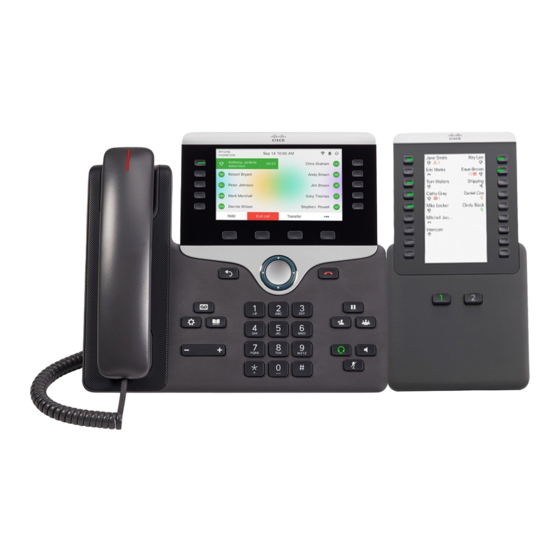
Accessories Overview for Cisco IP Phone 8800 Series with
Multiplatform Firmware
Table 1: Accessory Support for the Cisco IP Phone 8800 Series with Multiplatform Firmware
Accessory
Type
Cisco Accessory
Add-on
Cisco IP Phone 8800
Key Expansion
module
Module
Wall Mount Kit
Footstand
Cable Lock
Cisco Headset 520
USB
Series
Accessories Overview for Cisco IP Phone 8800 Series with Multiplatform Firmware, on page 1
Connect the Footstand, on page 3
Secure the Phone with a Cable Lock, on page 3
External Speakers and Microphone, on page 4
Headsets, on page 4
Cisco IP Phone Key Expansion Module, on page 13
Wall Mounts, on page 33
Cisco IP Phone
8811 and 8841
Not supported
Supported
Supported
Supported
Not supported
8845
8851
Not supported
Supported
Supports up to 2
expansion
modules.
Supported
Supported
Supported
Supported
Supported
Supported
Not supported
Supported
8861
8865
Supported
Supported
Supports up to 3 expansion
modules.
Supported
Supported
Supported
Supported
Supported
Supported
Supported
Supported
Cisco IP Phone Accessories
1
Advertisement

Related Manuals for Cisco 8800 Series


Summary of Contents for Cisco 8800 Series
- Page 1 Cisco IP Phone Accessories • Accessories Overview for Cisco IP Phone 8800 Series with Multiplatform Firmware, on page 1 • Connect the Footstand, on page 3 • Secure the Phone with a Cable Lock, on page 3 • External Speakers and Microphone, on page 4 •...
- Page 2 *—For the Bluetooth connection with Cisco IP Phone Multiplatform Phones, the limited call features (for example, answer or end a call) are available. The call features will be fully supported in a future release. Currently, we recommend that you use the Cisco Headset 730 by a USB adapter or a USB-C cable.
- Page 3 • The EHS connects to the Cisco IP Phone 8811, 8841, and 8845 with the auxiliary port. • The EHS connects to the Cisco IP Phone 8851, 8861, and 8865 with the auxiliary port, the USB port, or with Bluetooth.
- Page 4 Cisco Headsets 500 Series You can use the Cisco Headset 500 Series with your Cisco IP Phone 8800 Series Multiplatform Phones. The Cisco Headset 500 Series offers a more enhanced experience with: • In-call indicators: LEDs on an ear plate •...
- Page 5 Cisco Headset 521 and 522 The Cisco Headsets 521 and 522 are two wired headsets that have been developed for use on Cisco IP Phones and devices. The Cisco Headset 521 features a single earpiece for extended wear and comfort. The Cisco Headset 522 features two earpieces for use in a noisy workplace.
- Page 6 The Cisco Headset 560 Series use a headset base to connect with Cisco IP Phones and charge the headsets. The available options for the base are Standard base and Multibase. The Cisco Headset 560 Series with Standard Base support connection with a single source from a phone or a computer.
- Page 7 Cisco IP Phone Accessories Cisco IP Phone Accessories Figure 2: Cisco Headset 561 and 562 Headset Buttons The following table describes the Cisco Headset 561 and 562 Headset buttons. Table 3: Cisco Headset 561 and 562 Headset Buttons Number Name Description Use to power the headset on and off.
- Page 8 If the LEDs don't light up, remove the headset from the base and try again. Third Party Headsets Cisco Systems performs internal testing of third-party headsets for use with Cisco IP Phones. But Cisco does not certify or support products from headset or handset vendors.
- Page 9 Either the remote party or both the remote party and the Cisco IP Phone user may hear an audible hum or buzz. A range of outside sources can cause humming or buzzing sounds;...
- Page 10 Cisco doesn't recommend or test any third-party headsets with their products. For information about third-party headset support for Cisco products, go to the manufacturer's web site. Cisco does test the Cisco headsets with the Cisco IP Phones. For information about Cisco Headsets and Cisco IP Phone support, see https://www.cisco.com/c/en/us/products/collaboration-endpoints/headsets/index.html.
- Page 11 GHz band, which is the same as the 802.11b/g band. Cisco IP Phones use a shared key authentication and encryption method to connect up to fifty headsets, one at a time. The last connected headset is used as the default. Pairing is typically performed once for each headset.
- Page 12 When headsets are more than 30 feet (10 meters) away from the Cisco IP Phone, Bluetooth drops the connection after a 15- to 20-second timeout. If the paired headset comes back into range of the Cisco IP Phone and the phone is not connected to another Bluetooth headset, the in-range Bluetooth headset automatically reconnects.
- Page 13 Bluetooth as the preferred audio device. For information about how to use your Bluetooth wireless headset, see: • Cisco IP Phone 8811, 8841, 8851, and 8861 User Guide for Cisco Unified Communications Manager • User guides provided with your headset...
- Page 14 3; single LCD screen, 18 line keys, two pages, providing 108 buttons, Table 5: Cisco IP Phones and Supported Cisco IP Phone 8851/8861 Key Expansion Module and Cisco IP Phone 8865 Key Expansion Module Cisco IP Phone Model Supported Numbers of Key Expansion Modules and Buttons Cisco IP Phone 8851 2;...
- Page 15 Cisco IP Phone 8861, unless Cisco Universal PoE (UPoE) is used. • Cisco IP Phone 8851 with 2 key expansion modules works on 802.3at PoE only with v08 or later hardware. You can find the phone version information on the lower back of the phone as part of the TAN and PID label.
- Page 16 Cisco IP Phone Accessories Connect a Key Expansion Module to a Cisco IP Phone Table 7: Power-Supply Compatibility for Cisco IP Phone 8851/8861 Key Expansion Module and Cisco IP Phone 8865 Key Expansion Module Configuration 802.3af Power over Ethernet 802.3at PoE...
- Page 17 Position the phone so that the front of the phone faces up. Step 6 Connect one end of the key expansion module spine connector to the accessory connector on the Cisco IP Phone. a) Align the spine connector with the accessory connector ports.
- Page 18 Cisco IP Phone Accessories Cisco IP Phone Accessories This diagram shows the spine connector. This diagram shows the installation of the spine connector. Step 7 Connect the other end of the spine connector to the key expansion module as shown in this diagram.
- Page 19 Cisco IP Phone Accessories Cisco IP Phone Accessories Step 8 (Optional) Use a second key expansion module spine connector to connect the second key expansion module to the first key expansion module. Step 9 (Optional) Use a third key expansion module spine connector to connect the third key expansion module to the second key expansion module.
- Page 20 Cisco IP Phone Accessories Connect Two or Three Key Expansion Modules to a Cisco IP Phone Note Make sure that the screws are fully inserted into the phone and tightened. If you lose any screws, the phone uses a standard M3 0.5x5.0mm screw.
- Page 21 Position the phone so that the front of the phone faces up. Step 6 Connect one end of the key expansion module spine connector to the accessory connector on the Cisco IP Phone. a) Align the spine connector with the accessory connector ports.
- Page 22 Step 9 Use a third key expansion module spine connector to connect the third key expansion module to the second (middle) key expansion module. This figure shows a Cisco IP Phone with three key expansion modules attached. Cisco IP Phone Accessories...
- Page 23 When a user adds key expansion modules to these phones, the module lights up and is enabled automatically. Default value of this field is 2 for Cisco IP Phone 8851 and 3 for Cisco IP Phone 8861.
- Page 24 Cisco IP Phone Accessories Configure the Key Expansion Module with the Phone Web Interface Configure the Key Expansion Module with the Phone Web Interface You can add number of supported key expansion modules from the phone web interface. You can also configure the parameters in the phone configuration file with XML(cfg.xml) code.
- Page 25 Cisco IP Phone Accessories Allocate a Key Expansion Module Type Allocate a Key Expansion Module Type You can assign the type of key expansion module that the phone supports: • BEKEM • CP-8800-Audio • CP-8800-Video You can also configure the parameters in the phone configuration file with XML(cfg.xml) code.
- Page 26 Reset the Single LCD Screen Key Expansion Module Reset the Single LCD Screen Key Expansion Module If you are having technical difficulties with your Cisco IP Phone 8800 Key Expansion Module, you can reset the module to the factory default settings.
- Page 27 Cisco IP Phone Accessories Add Call Park on a Key Expansion Module Line Key You can also configure the parameter in the configuration file (cfg.xml) by entering a string in the following format: <Unit_n_Key_m>fnc=sd;ext=9999@$PROXY;vid=n;nme=xxxx Step 4 Click Submit All Changes.
- Page 28 Cisco IP Phone Accessories Configure the Busy Lamp Field on a Key Expansion Module Before you begin Access the phone administration web page. See Access the Phone Web Interface. Procedure Step 1 Select Voice > Att Console. Step 2 Set the Attendant Console LCD Contrast to a value between 1 and 15.
- Page 29 Cisco IP Phone Accessories Enable the User to Configure Features on Key Expansion Module Line Keys Where: sd= speed dial cp= call pickup You can also enable busy lamp field only with call pickup or speed dial. Enter the string in the following format: fnc=blf+cp;sub=xxxx@$PROXY;usr=yyyy@$PROXY...
- Page 30 Cisco IP Phone Accessories Add a Menu Shortcut to a Key Expansion Module Line Key Step 3 Click Submit All Changes. Add a Menu Shortcut to a Key Expansion Module Line Key You can add a menu shortcut to a line key of the attached key expansion module. Then, the user can press the configured line key to access the menu.
- Page 31 Cisco IP Phone Accessories Configure the Voicemail PLK on a Key Expansion Module Button Procedure Step 1 Select Voice > Att Console. Step 2 Go to the Unit (n) section, where n is unit number of the key expansion module.
- Page 32 Cisco IP Phone Accessories Troubleshoot the Key Expansion Module • For MWI + speed dial + DTMF: fnc=mwi+sd;ext=8000 ,4085283300#,123456#@domain;sub=group_vm@domain;vid=1;nme=Group; For more information about the string syntax, see String Syntax for Voicemail PLK. You can also configure this parameter in the phone configuration file (cfg.xml). The parameter is line-specific.
- Page 33 The following wall mount options are available: • Cisco IP Phone 8800 Series Wall Mount Kit: A nonlockable wall mount kit available for the Cisco IP Phone 8800 Series. This wall kit applies to Cisco IP Phone 8811, 8841, 8851, and 8861. The PID is CP-8800-WMK=.
- Page 34 Non-Lockable Wall Mount Components • Cisco IP Phone 8800 Series Wall Mount Kit with Single KEM: The kit is installed on the Cisco IP Phone 8851, and 8861 with one attached Cisco IP Phone 8800 Key Expansion Module. The PID is...
- Page 35 Cisco IP Phone Accessories Install the Non-Lockable Wall Mount Kit for Phone Figure 7: Back view of Wall Mount Kit Installed on Phone The following figure shows the phone with the wall mount kit from the side. Figure 8: Side View of Wall Mount Kit Installed on Phone Install the Non-Lockable Wall Mount Kit for Phone The wall mount kit can be mounted on most surfaces, including concrete, brick, and similar hard surfaces.
- Page 36 Cisco IP Phone Accessories Cisco IP Phone Accessories You must also install an Ethernet jack for the telephone in the desired location if an Ethernet jack does not currently exist. This jack must be wired appropriately for an Ethernet connection. You cannot use a regular telephone jack.
- Page 37 Cisco IP Phone Accessories Cisco IP Phone Accessories a) Detach power cord, and any other attached cords from the base of the phone, except the handset cord (and headset cord, if there is a headset). b) Attach the phone bracket by inserting the tabs into the mounting tabs on the back of the phone. The phone ports should be accessible through the holes in the bracket.
- Page 38 Cisco IP Phone Accessories Cisco IP Phone Accessories Figure 11: Attach Cables The following figure shows the cables. Step 4 Attach the phone to the wall bracket by inserting the tabs on the top of the wall bracket into the slots on the phone bracket.
- Page 39 Cisco IP Phone Accessories Remove the Phone from the Non-Lockable Wall Mount Step 5 Press the phone firmly into the wall bracket and slide the phone down. The tabs in the bracket click into position. Step 6 Proceed to Adjust the Handset Rest, on page Remove the Phone from the Non-Lockable Wall Mount The wall bracket has two tabs that lock the kit together.
- Page 40 Non-Lockable Wall Mount Components for Phone with Key Expansion Module This section describes how to install the Cisco IP Phone 8800 Series Wall Mount Kit with Single KEM on a phone when the phone is connected to a Key Expansion Module.
- Page 41 Cisco IP Phone Accessories Install Non-Lockable Wall Mount Kit for Phone with Key Expansion Module The following figure shows the components of the Cisco IP Phone 8800 Series Wall Mount Kit with Single KEM. The package contains the following items: •...
- Page 42 Cisco IP Phone Accessories Cisco IP Phone Accessories • #1 and #2 Phillips-head screwdrivers • Level • Pencil You must also install an Ethernet jack for the telephone in the desired location if an Ethernet jack does not currently exist. This jack must be wired appropriately for an Ethernet connection. You cannot use a regular telephone jack.
- Page 43 Cisco IP Phone Accessories Cisco IP Phone Accessories Step 2 Attach the phone bracket to the IP phone and key expansion assembly. a) Detach power cord, and any other attached cords from the base of the phone, except the handset cord (and headset cord, if there is a headset).
- Page 44 Cisco IP Phone Accessories Cisco IP Phone Accessories Step 3 Attach the cords. a) Attach the Ethernet cable to the 10/100/1000 SW network port and wall jack. b) (Optional) If you are connecting a network device (such as a computer) to the phone, attach the cable to the 10/100/1000 Computer (PC access) port.
- Page 45 Cisco IP Phone Accessories Remove the Phone and Key Expansion Module from the Non-Lockable Wall Mount For cables that terminate outside of the bracket, use the cable-access openings in the bottom of the bracket to position the power cord and any other cable that does not terminate in the wall behind the bracket. The phone and wall bracket openings together form circular openings with room for one cable per opening.
- Page 46 Cisco IP Phone Accessories Adjust the Handset Rest Procedure Step 1 Insert a screw driver or other device into the left and right holes in the phone mounting plate. Insert to a depth of about 3/4 of an inch or 2 centimeters.
- Page 47 Cisco IP Phone Accessories Cisco IP Phone Accessories Procedure Step 1 Remove the handset from the cradle and pull the plastic tab from the handset rest. Step 2 Rotate the tab 180 degrees. Step 3 Hold the tab between two fingers, with the corner notches facing you.
- Page 48 Cisco IP Phone Accessories Cisco IP Phone Accessories Cisco IP Phone Accessories...
Need help?
Do you have a question about the 8800 Series and is the answer not in the manual?
Questions and answers