
Related Manuals for Omtech USB1410a


Summary of Contents for Omtech USB1410a
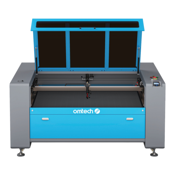
- Page 1 V20241021 USB1410a | 130W | CO Cabinet Laser Engraver User Manual Read Carefully Before Use Keep for Future Reference...
- Page 2 BEAMING WITH POSSIBILITIES! Thank you for choosing omtech! Your new CO ₂ laser engraving machine is intended for personal and professional use. When used following these instructions, it comprises a CLASS 1 laser system but some components remain extremely dangerous. Never disable the preinstalled safety engravers and always use your laser safely and responsibly.
-
Page 3: Help Center
Welcome to the OMTech Community! For helpful hints and instructional videos, visit our Help Center or join our official laser group! If you encounter any issues with your engraver, please feel free to contact us. Our support team will respond ASAP to resolve your concerns. -
Page 4: Table Of Contents
Content 1 Safety Information .................... 1 Disclaimer ..............................1 Symbol Guide ............................. 2 General Safety Instructions ........................3 1.4 Laser Safety Instructions ......................... 4 Electrical Safety Instructions ........................5 1.6 Material Safety Instructions ........................6 Disposal Safety Instructions ........................6 2 Introduction ...................... - Page 5 4 Operation ......................37 4.1 Operation Overview ..........................37 4.2 Pre-Operation Preparation ........................38 4.2.1 Turning on the Machine ......................38 4.2.2 Preparing Material ........................39 4.2.3 Preparing the Engraving Pattern ..................... 40 4.2.4 Focusing ............................41 4.3 Engraving Proper ............................41 4.4 Wrapping-up ...............................
- Page 6 Content 4.7.15 Loading Saved Parameter ......................57 4.7.16 Autofocus ............................57 4.7.17 Setting the Interface Language ....................58 4.7.18 Setting the Machine’s IP Address .................... 58 4.7.19 Diagnostic Tools ........................... 59 4.7.20 Reflecting Images across an Axis .................... 59 4.7.21 Resetting Axes ..........................60 4.7.22 Alarm Displays ..........................
-
Page 8: Safety Information
Read this disclaimer completely and carefully before proceeding with the rest of the manual content. As-Is This OMTech product is sold ‘as is’ and without any express or implied warranties, including but not limited to the implied warranties of merchantability and fitness for a particular purpose. -
Page 9: Symbol Guide
1.2 Symbol Guide The following symbols are used on this machine’s labeling or in this manual: These items present a risk of serious property damage or personal injury. These items address similarly serious concerns about the laser beam. These items address similarly serious concerns about electrical components. These items address similarly serious concerns about fire hazards. -
Page 10: General Safety Instructions
1 Safety Information 1.3 General Safety Instructions • Your device should come with instruction labels in the following locations: SH-G1490 900*600mm 130W 110V USB-1409-US If any of these labels is missing, illegible, or becomes damaged, it must be replaced. • Use this laser engraving device only in accordance with all applicable local and national laws and regulations. -
Page 11: Laser Safety Instructions
• DO NOT allow minors, untrained personnel, or personnel suffering from physical or mental impairment that would affect their ability to follow this manual and the software manual to install, operate, maintain, or repair this device. • Any untrained personnel who might be near the device while it is in operation MUST be informed that it is dangerous and fully instructed on how to avoid injury during its use. -
Page 12: Electrical Safety Instructions
1 Safety Information • ONLY use this engraver if its automatic shutoffs are working properly. When you first get this engraver and if you subsequently notice any problems, test them (see below) before undertaking any other work. Do not continue use if the shutoffs do not occur. Turn off the device and contact customer service or your repair service. -
Page 13: Material Safety Instructions
• Do not handle your water pump or the water in which it is submerged while the pump is attached to its power supply. Place it in water before connecting it to power and disconnect it from power before removing it. •... -
Page 14: Introduction
2 Introduction 2.1 General Information This manual is the designated user guide for the installation, setup, safe operation, and maintenance of your cabinet laser engraver. It is divided into six chapters covering general information, safety instructions, installation steps, operation instructions, maintenance procedures, and contact information. -
Page 15: Specifications
2.3 Specifications Name USB1410a, 130W, CO2 Cabinet Laser Engraver Model USB1410a Input Power AC 110–120 (V), 60 Hz Power Consumption 1500 W Laser Output Power 130 W Expected Service Life at <40% / 40–70% / >70% Power 12,000 / 10,000 / 8,000 hr. -
Page 16: Components
2 Introduction 2.4 Components 2.4.1 Package List... - Page 17 Item Qty. Power Cord Ground Wire USB Cable Ethernet Cable Laser Keys Door Keys USB Flash Drive with Engraving Software Included Ø 150 mm Exhaust Pipes Ø 150 mm Pipe Clamps A Set of Hex Wrenches Silicone Sealant Acrylic Focusing Tool Ceramic Testing Resistor Water Hoses Water Hose Clamps...
-
Page 18: Main Parts
2 Introduction 2.4.2 Main Parts... - Page 19 The cover provides access to the main bay for placing and retrieving materials, as Cover well as fixing the laser path alignment and other maintenance. Power to the laser is automatically cut when the cover is opened. The polycarbonate window is shielded to protect you and others from the laser and its Viewing Window reflection, allowing monitoring of the engraving process.
-
Page 20: Laser Path
2 Introduction 2.4.3 Laser Path This CO ₂ -filled glass tube is mounted on brackets and immobile. Its Laser Tube connection to the laser power supply is extremely high voltage and extremely dangerous. This adjustable-angle mirror is fixed in place to transfer the engraving laser 1st Mirror from the tube to the 2nd mirror. -
Page 21: Laser Head
2.4.4 Laser Head This adjustable-angle mirror transfers the laser from the 2nd mirror to 3rd Mirror the focus lens. This rail moves along the Y axis, with its movement controlled by limit X-Axis Rail switches. Red Dot Pointer This device helps you see the exact position of the invisible engraving laser. This 18 mm lens directs and focuses the laser beam to its point of Focus Lens contact with the engraving material. -
Page 22: Control Panel
2 Introduction 2.4.5 Control Panel Front Right When the system is idle or the work is finished, all the buttons can be used. Users can process the file, set the parameters, preview their file, etc. When the work is running or paused, some buttons will not work, e.g., Origin and Frame. - Page 23 Returns the machine to the saved default parameters (see § 4.7.14 Saving Current Parameters and Virtual Keyboard Use on Page 57). Starts/pauses the current job. Stops the current job. Stops work or returns to a previous menu. Enters a command or confirms your selection. Opens the main menu (see §...
-
Page 24: Screen Display
2 Introduction 2.4.6 Screen Display... - Page 25 Design Display Shows the whole file’s track and the running track. Parameters Displays the running file’s fi le number, speed, max power, etc. Coordinates Displays the current coordinates of the laser head. Displays the layer parameters of current or previewed fi les. Layers Parameters from left to right are layer number, color, speed, and maximum power.
-
Page 26: Connection Inputs
2 Introduction 2.4.7 Connection Inputs Back Right This port allows you to load and save designs and parameters USB Port directly onto the engraver. This port connects to your control computer and its engraving USB Line Port software using any of its USB ports. This port connects to your control computer and its software Ethernet Port either directly or via the internet. - Page 27 This port connects to the dedicated grounding cable for safety Ground if applicable. This port connects to the 3-prong main power cable. ONLY the TWO power cables are plugged, can the machine work 2nd Main Power Port normally. The two power cords should be plugged into a compatible and stable power source via grounded 3-prong outlets on SEPARATE circuits rated for at least 10 A.
-
Page 28: Electronics Bay
2 Introduction 2.4.8 Electronics Bay Front Right This circuit board controls the engraving process, responding Mainboard to commands from your engraving software or the machine’s control panel. Y-Axis Driver This device moves the X rail along the Y rail. X-Axis Driver This device moves the laser head along the X rail. -
Page 29: Laser Power Supply
2.4.9 Laser Power Supply Front Left This line is connected to the laser tube’s anode or positive High-Voltage Wire end, providing high-voltage current to power the laser. Mounting Holes These standard slots allow simple installation and removal. When connected, this light shows the water cooling system Water Indicator Light is operating. -
Page 30: Installation
3 Installation 3.1 Installation Overview A complete working system consists of the following parts: • A laser engraving cabinet The cabinet can use designs provided by the enclosed engraving software by direct or internet connection with your computer; it can also engrave designs loaded directly from a flash drive. •... -
Page 31: Unpacking Your Engraver
• Depending on the materials to be processed, this may require the construction of a dedicated ventilation system. • The location should be away from children; combustible, flammable, explosive, or corrosive materials; and sensitive EMI machines. • The two power cords should be plugged into a compatible and stable power source via grounded 3-prong outlets on SEPARATE circuits rated for at least 10 A. -
Page 32: Installing The Water Cooling System (Not Included)
3 Installation 3.4 Installing the Water Cooling System (Not Included) A water cooling system—typically a water pump or chiller—MUST be used with this engraver to absorb the heat produced by the laser tube. The water cooling system is essential to your engraver’s performance and longevity. -
Page 33: Installing The Exhaust System
3.5 Installing the Exhaust System This machine is equipped with two duct fans inside, you need to install the provided exhaust pipes directly onto the exhaust fans to use the machine. Firmly connect one of the engraver’s exhaust ports to the provided exhaust pipe by using one pipe clamp. -
Page 34: Connecting To Power Supply
3 Installation 3.6 Connecting to Power Supply Confirm that the labeling beside the power socket at the back of the engraver matches your local power supply. 2. Connect one end of the power cable to the power socket. 3. Plug the other end of the power cable into a grounded 3-prong outlet or into a surge protector rated over 2000 J that is itself connected to a grounded outlet. -
Page 35: Setting Up Your Control Computer
3.7 Setting Up Your Control Computer See the software manual for details on the requirements for the control computer. The control computer can be connected directly using the provided USB. The control computer should not be placed more than 15 feet (4.5 m) away to avoid possible interference with the signal on its line. A Windows-compatible copy of RDworks V8 is provided on the USB flash drive that came with your engraver. -
Page 36: Rdworks V8
3 Installation 3.7.1 RDWorks V8 I n i t i a t e R D Wo r k s V 8 o n y o u r c o n t r o l computer and connect it to the engraver using the provided USB cable. - Page 37 Click “Test” in the dialogue box that shows up as shown. The connection is successful when the pop- up as shown shows up. Click OK to confirm the connection and close the dialogue box. Click “Exit” to return to the home interface.
-
Page 38: Lightburn
3 Installation 3.7.2 Lightburn Initiate Lightburn on your control computer and connect it to your engraver using the provided USB cable. Click “Device” as shown. Click “Create Manually” in the pop-up that shows up. - Page 39 Choose “Ruida” and click “Next”. Choose Serial/USB and then “Next”.
- Page 40 3 Installation Enter the circled engraver name and X and Y axis length. Click “Next”. USB1410a 1400 Set the origin to “Rear Right” as shown and click “Next”.
- Page 41 Confirm your configuration and click “Finish” to close the pop-up. USB1410a 1400mm x 900mm Click the device drop list in the lower right corner and choose “PRO 3655”. The engraver is connected when the system shows “Ready”. USB1410a...
-
Page 42: Initial Testing
3 Installation 3.8 Initial Testing 3.8.1 Emergency Shutoff Because of the risk of fire and other hazards during engraving, this engraver includes a large and easy-to-reach emergency stop button near the control panel. Press it down to stop the laser tube instantly. -
Page 43: Water Shutoff
After ensuring that the emergency stop button works, you should also test that the cover shutoff works properly before conducting any other work on your machine. Start the water cooling system, place a piece of laserable scrap material on the workbed, close the cover, and press Pulse to fire the laser. -
Page 44: Operation
4 Operation 4.1 Operation Overview Operate this laser engraver only in accordance with all the instructions provided in this manual. Failure to follow these instructions can result in property damage and personal injury. Wear safety glasses during the entire test process! This section will address only some of the options and features provided by the operation software. -
Page 45: Pre-Operation Preparation
4.2 Pre-Operation Preparation 4.2.1 Turning on the Machine Make sure the power supply is ok. 2. Turn on your water cooling system. 3. (Optional) Turn on your additional ventilation system (such as a dedicated purifier). 4. On the control panel, slightly rotate the emergency stop button counterclockwise until it pops up. -
Page 46: Preparing Material
4 Operation 4.2.2 Preparing Material Open the engraver’s cover. 2. Place a sample piece of your material on the workbed. The default location of the laser head’s zero position is at the top left corner of the workbed. This can be changed by moving either your design or the engraver’s origin position using the §... -
Page 47: Preparing The Engraving Pattern
4.2.3 Preparing the Engraving Pattern Create the design. You can do this directly in your engraving software or use any other graphics program, saving or converting the file to a format compatible with the engraver. See the full list of acceptable file §... -
Page 48: Focusing
4 Operation 4.2.4 Focusing Open the cover to check that your sample material is still on the workbed. 2. Place the acrylic focus tool on top of the material and carefully raising the workbed. The laser head should barely touch the top of the acrylic tool without applying any pressure, ensuring the engraving distance is correct. -
Page 49: Wrapping-Up
4.4 Wrapping-up Once you have finished engraving, close your software and then turn off your machine in the following order: a. Close your engraving software, and unplug the USB cable or ethernet cable. b. Turn and remove your laser key. c. -
Page 50: Engraving Procedures With A Rotary Attachment
4 Operation 2. Place your rotary axis in an open area. 3. Put the material and adjust the position using the rotary axis’ knobs. 4. Check the height of the workbed is appropriate. If necessary, lower the workbed to provide room for the laser head to pass over your axis and material. -
Page 51: Engraving Proper
4.5.3 Engraving Proper Do the pre-operation steps per § 4.2 Pre-Operation Preparation on Page 38. 2. Turn on the switch of your rotary attachment. The rotation of the rotary attachment will be controlled by the engraver’s Y axis settings. § 4.3 Engraving Proper §... -
Page 52: Leather
4 Operation 4.6.3 Leather When engraving leather products, generally use low to moderate power at high speed. Be especially attentive to the possibility of fire, as well as the dust produced in repetitive applications. 4.6.4 Metal CO ₂ laser engravers should not be used for marking, engraving, or cutting metal. They are best suited for working coatings applied to a metal base, and care must be taken not to attempt work on the underlying metal itself. -
Page 53: Stone
4.6.8 Stone When engraving various kinds of stone, generally use moderate power and moderate to fast speed. As with ceramics and glass, be mindful of the dust created (especially for repetitive industrial applications) and take similar measures to ensure the safety of users and others in the work area. 4.6.9 Textiles When engraving textiles like cloth and fleece, generally use low power and fast speed. -
Page 54: Control Panel Instructions
4 Operation 4.7 Control Panel Instructions 4.7.1 Overview You can control your engraver directly from the built-in control panel, through a direct connection with your computer, or over the internet. For details on operating your engraving software, see its separate manual. The built-in control panel can operate the laser manually or engrave designs loaded onto flash drives and external hard drives connected to the USB port on the right side of the cabinet. - Page 55 To load a design from a FAT16 or FAT32 formatted flash disk or external hard drive, press MENU, select “File”, then “Udisk+” and then “Copy to Memory”. Select the design in the File menu and then select “Run”. Various parameters can be adjusted using the console's menus and submenus, including setting multiple origin points to engrave the design on your material four times in a single session.
-
Page 56: Menu Button
4 Operation 4.7.2 Menu Button Press MENU on the main interface to enter the Menu interface: Push the ▲ and ▼ keys to select items, and then press ENTER to enter the corresponding submenu. 4.7.3 Setting the Laser Speed Select “Speed” on the Menu interface, and the following dialogue box will appear: The cursor will appear when pushing the ◄... -
Page 57: Setting The Laser Power
4.7.4 Setting the Laser Power Select “Max Power” or “Min Power” on the Menu interface, and the following dialogue boxes will appear: Push the ◄ and ► and ▲ and ▼ keys to change the parameters. See the “Speed” setting for reference. -
Page 58: File Commands
4 Operation 4.7.5 File Commands Select “File” on the Menu interface, and the following dialogue box will appear: When entering the above interface, the system automatically reads the memory files. The file name and the work times will be listed, and the selected file will be previewed in the upper right corner. When there are several files, use the ▲... -
Page 59: Flash Drive Commands
Select "Other" and press ENTER, and the following dialogue box will pop up: • Current Work Time forecasts the running time of the current file • Clear All Count clears the count of every file in the memory • Delete All Files deletes all files from memory •... -
Page 60: Adjusting Engraving Layers
4 Operation 4.7.7 Adjusting Engraving Layers When the system is idle or the work is finished, press ENTER to enter the layer parameter section. Push the ▲ and ▼ keys to select the intended layer. Press ENTER to check the selected layer’s parameters as shown below: The light blue cursor will be on “Layer”... -
Page 61: Adjusting The Z Axis
4.7.9 Adjusting the Z Axis When the light blue cursor is on “Z move”, push the ◄ and ► keys to control the movement of the Z-axis. 4.7.10 Setting an Interface Password When the light blue cursor is on this item, press ENTER, and the following dialogue box will pop up: Push the ▲... -
Page 62: Manual Movement Of The Laser Head
4 Operation 4.7.11 Manual Movement of the Laser Head When the light blue cursor is on “Manual Set+”, press ENTER, and the following dialogue box will pop up: When the light blue cursor is on “Mode”, push the ◄ and ► keys to choose between the two modes “Continue”... -
Page 63: Setting Origin Points
4.7.13 Setting Origin Points When the light blue cursor is on “Origin Set+”, press ENTER, and the following dialogue box will pop up: Press FN to move the light blue cursor to an item and press ENTER to enable or disable the item. When enabled, the small box will be red and, when disabled, the small box will be gray. -
Page 64: Saving Current Parameters And Virtual Keyboard Use
4 Operation 4.7.14 Saving Current Parameters and Virtual Keyboard Use When the light blue cursor is on the “Set Fact Para” item, press ENTER, and the following dialogue box will pop up: The password consists of six characters. Push the ▲ and ▼ and ◄ and ► keys to select each character, and press ENTER to confirm each selection. -
Page 65: Setting The Interface Language
4.7.17 Setting the Interface Language When the light blue cursor is on this item, press ENTER, and the following dialogue box will pop up: The operation method is the same as described above. Press ENTER when one language is selected, and then return to the main interface. 4.7.18 Setting the Machine’s IP Address When the light blue cursor is on this item, press ENTER, and the following dialogue box will pop up: Press FN to move the light blue cursor to the intended item, and push the ▲... -
Page 66: Diagnostic Tools
4 Operation 4.7.19 Diagnostic Tools When the light blue cursor is on this item, press ENTER, and the following dialogue box will pop up: This interface contains input/output information of the system’s hardware. Press the “Read Para” button to access hardware information. When the hardware signal is triggered, the small box to the left of the corresponding item will be displayed in green. -
Page 67: Resetting Axes
4.7.21 Resetting Axes When the green block is on this item, press ENTER, and the following dialogue box will pop up: Push the ▲ and ▼ keys to move the light blue block to the intended item. Press ENTER to start the resetting of the selected axis. -
Page 68: Maintenance
5 Maintenance 5.1 Maintenance Overview • The use of procedures other than those specified herein may result in hazardous laser radiation exposure. • Before any cleaning or maintenance work, always switch off the device and disconnect it from its power supply. •... -
Page 69: Cleaning The Main Bay And Engraver
5.2.2 Cleaning the Main Bay and Engraver Cleaning Frequency: Daily, after each use • Disconnect the engraver from power before cleaning. • Completely wipe dry the surfaces after cleaning. • NEVER allow water to come into contact with the electronic elements. Depending on what you’ve been engraving, you might need to clean the engraver more or less often. -
Page 70: Cleaning The Focus Lens
5 Maintenance 5.2.3 Cleaning the Focus Lens The lens has a durable coating and won’t be damaged by correct and careful cleaning. If not clean, your laser will be less efficient and heat buildup on the oil or dust itself can damage the lens. Cleaning Frequency: Daily, after each use Tools Needed: •... - Page 71 2. Move the laser head into the center of the workbed and put a cloth under the lens holder so that the lens will not be damaged if it accidentally falls from its holder. 3. Remove the pressurized air hose by pulling it out.
- Page 72 5 Maintenance 4. Take out the lens holder by rotation. Lens Holder 5. Remove the nozzle by rotating it toward you. Nozzle...
- Page 73 6. Remove the lens from the lens holder by using the lens removal tool (P) and letting the lens and its O-ring drop onto the cleaning cloth. Focus Lens Focus Lens Repair Tool Cleaning the Focus Lens and Its O-Ring Examine the lens surface, remove coarse dust as well as possible by blowing air onto the lens surface and, if necessary, clean it with the lens cleaning liquid and lens tissue or cloth as below.
-
Page 74: Cleaning The Mirrors
5 Maintenance Reattaching the Focus Lens Carefully insert the lens into the lens holder, ensuring that its rounded convex side is facing upwards. 2. Put the O-ring on top of the lens. 3. Carefully reassemble nozzle, the lens holder, the red dot pointer and the air hose in reverse order. - Page 75 Mirror Name Mirror Location Cleaning Method In the back left of the 1st Mirror machine beyond the far end of the Y axis On the Y axis at the 2nd Mirror left end of the X axis Clean with lens-cleaning tissue or with cotton wetted with lens-cleaning liquid or isopropyl alcohol in gentle circular motions.
-
Page 76: Cleaning The Exhaust System
5 Maintenance 5.2.5 Cleaning the Exhaust System Check and clean the exhaust pipes and fans. The rate of dust accumulation on the exhaust fan and pipe will vary depending on the materials processed and the working environment’s air quality. Cleaning Frequency: Weekly Tools Needed: •... -
Page 77: Laser Path Alignment
5.3 Laser Path Alignment Having a perfectly aligned laser path is paramount to your engraver’s overall performance. Each of the pro-line series went through a complete beam alignment before shipping. Upon first arrival and about once a week during normal operation, however, it is recommended that the alignment be checked. -
Page 78: Laser Tube Alignment
5 Maintenance Place a piece of tape at each stage of the laser path. DO NOT place the tape directly onto the mirror. 2. Turn on the machine. 3. Set the Max. Power (not Min.) parameter to 15% or lower. Any higher percentage will cause the laser to ignite the testing tape instead of marking it. - Page 79 4. Press Pulse to manually fire the laser and observe if the laser mark is centered on the tape as below. If so, then the laser tube is aligned with the 1st Mirror; if not, continue to step 5. You should be able to see a small mark on the tape. If it is not noticeable, press Pulse again.
-
Page 80: 1St Mirror Alignment
5 Maintenance 5.3.2 1st Mirror Alignment • Wear safety goggles during the entire aligning process. • Avoid attaching the tape directly to any of the mirrors. • Less than 15% of the maximum power (not Min.) should be sufficient to leave a clear mark without setting the testing tape on fire. - Page 81 4. Adjust the 1st mirror’s set setscrews accordingly. a. Loosen the nut on the setscrew. b. Slightly turn the setscrew either clockwise or counterclockwise. Setscrew Lower Beam Raise Beam Move Beam Left Lower Beam Right • Each screw adjusts a different position or angle. •...
-
Page 82: 2Nd Mirror Alignment
5 Maintenance 5.3.3 2nd Mirror Alignment After ensuring the laser is well aligned between the 1st mirror and the 2nd mirror, check the alignment between the 2nd mirror and the 3rd mirror. Use the direction arrows on the control panel to send the 3rd mirror to the left of the bed along the X axis. -
Page 83: 3Rd Mirror Alignment
5.3.4 3rd Mirror Alignment • Wear safety goggles during the entire aligning process. • Avoid attaching the tape directly to the mirror. • Less than 15% of the maximum power (not Min.) should be sufficient to leave a clear mark without setting the testing tape on fire. •... -
Page 84: Lubrication
5 Maintenance 5.4 Lubrication 5.4.1 Rails Lubrication Frequency: Every two weeks Tools Needed: • Cotton cloth • White lithium grease Disconnect the engraver from power. 2. Gently move the laser head out of the way. 3. Wipe away all dust and debris along the X and Y axis rails with a dry cotton cloth until they are shiny and clean. -
Page 85: Parts Replacement
5.5 Parts Replacement • Be sure only to use identical or compatible replacement parts with this engraver. Contact your vendor or our technicians if you have any questions about fitment. Using incompatible components is highly dangerous and waives all the manufacturer’s liability for any damage or injury caused. •... - Page 88 Scan for the latest user manual USB1410a | 130W | CO Cabinet Laser Engraver User Manual U S B -1 4 0 9 - U S R e v. 2 1 O c t . 2 0 2 4...
Need help?
Do you have a question about the USB1410a and is the answer not in the manual?
Questions and answers