
Subscribe to Our Youtube Channel
Related Manuals for Technosoft Micro 4803 MZ


Summary of Contents for Technosoft Micro 4803 MZ
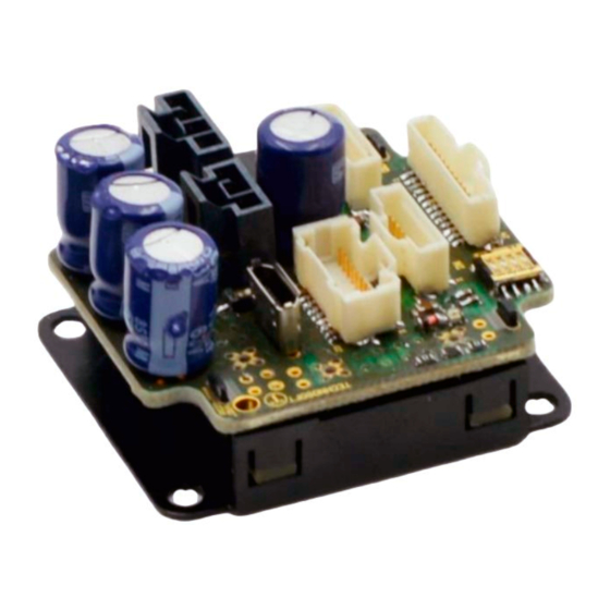
- Page 1 Micro 4803 MZ / PZ / CZ / HZ Intelligent Servo Drives Intelligent Servo Drive for DC, Brushless DC and AC Motors Technical Reference © Technosoft 2023 P091.020.Micro 4803 MZ.PZ.CZ.HZ.UM.0523A...
- Page 2 Micro 4803 MZ/PZ-CAT connection diagram ................ 27 ..3.7.3 Micro 4803 CZ-CAN connection diagram ................28 ..3.7.4 Micro 4803 CZ-CAT connection diagram ................28 ..© Technosoft 2023 Micro 4803 MZ / PZ / CZ / HZ Technical Reference...
- Page 3 Axis ID Selection and Operation Mode ..............58 3.19.1 Axis ID Selection for Micro 4803 MZ/PZ-CAT ............... 58 ..3.19.2 Axis ID Selection and Operation Mode for Micro 4803 MZ/PZ-CAN ........59 ..3.19.3 Axis ID Selection for Micro 4803 CZ-CAT ................60 ..
- Page 4 CAN-Bus for CAN executions ................65 4.18 EtherCAT ports for CAT execution ................ 65 4.19 Conformity ....................... 65 De-rating curves ..................... 66 Memory Map ......................67 © Technosoft 2023 Micro 4803 MZ / PZ / CZ / HZ Technical Reference...
- Page 5 Whilst Technosoft believes that the information and guidance given in this manual is correct, all parties must rely upon their own skill and judgment when making use of it. Technosoft does not assume any liability to anyone for any loss or damage caused by any error or omission in the work, whether such error or omission is the result of negligence or any other cause.
- Page 6 TML motion programming and motion evaluation tools. Help of the EasySetUp software – describes how to use EasySetUp to quickly setup any Technosoft drive for your application using only 2 dialogues. The output of EasySetUp is a set of setup data that can be downloaded into the drive EEPROM or saved on a PC file.
- Page 7 THE DRIVE MAY HAVE HOT SURFACES DURING OPERATION. DURING DRIVE OPERATION, THE CONTROLLED MOTOR WILL MOVE. KEEP WARNING! AWAY FROM ALL MOVING PARTS TO AVOID INJURY © Technosoft 2023 Micro 4803 MZ / PZ / CZ / HZ Technical Reference...
- Page 8 (Registration, Evaluation, Authorization and Restriction of Chemicals), which came into force on 01.06.2007. RoHS Compliance - Technosoft SA here with declares that this product is manufactured in compliance with the RoHS directive 2002/95/EC on the restriction of the use of certain...
- Page 9 11 bit identifiers. When TMLCAN mode is selected, the unit behaves as standard Technosoft intelligent drive and conforms to Technosoft protocol for exchanging TML commands via CAN-bus. When TMLCAN protocol is used, it is not mandatory to have a master.
- Page 10 Hence neither the Micro 4803 TML programming capability nor the drive camming mode are used. EasySetUp can be downloaded free of charge from Technosoft web page. EasyMotion Studio platform includes EasySetUp for the drive setup, and a Motion Wizard for the motion programming.
- Page 11 • Incremental encoder interface: • Micro 4803 MZ/PZ/HZ: Incremental A / B: differential or single-ended • Micro 4803 CZ: Incremental A / B: differential • Pulse & direction interface for external (master) digital reference • Absolute: differential or single-ended encoder. Supported protocols: SSI, BiSS, EnDAT, TAMAGAWA, Panasonic, Nikon, Sanyo Denki •...
- Page 12 Micro 4803 MZ-CAT P020.001.E122 Micro 4803 MZ-CAN P020.001.E102 Micro 4803 PZ-CAT P020.001.E322 Micro 4803 PZ-CAN P020.001.E302 Micro 4803 CZ-CAT P020.801.E222 Micro 4803 CZ-CAN P020.801.E202 Micro 4803 HZ-CAN P020.001.E202 © Technosoft 2023 Micro 4803 MZ / PZ / CZ / HZ Technical Reference...
- Page 13 Load encoder is on Feedback 2 / 1, if motor encoder is on Feedback 1 / 2 Load encoder can be only on Feedback 1 Load encoder can be only on Feedback 2 © Technosoft 2023 Micro 4803 MZ / PZ / CZ / HZ Technical Reference...
- Page 14 Hardware Installation Micro 4803 MZ Dimensions Figure 5 Micro 4803 MZ dimensions Micro 4803 PZ Dimensions Figure 6 Micro 4803 PZ dimensions © Technosoft 2023 Micro 4803 MZ / PZ / CZ / HZ Technical Reference...
- Page 15 Micro 4803 HZ Dimensions Figure 7 Micro 4803 HZ dimensions Micro 4803 CZ Dimensions Figure 8 Micro 4803 CZ dimensions © Technosoft 2023 Micro 4803 MZ / PZ / CZ / HZ Technical Reference...
- Page 16 Mechanical Mounting The Micro 4803 MZ/PZ is intended to be mounted horizontally on a motherboard equipped with the recommended mating connectors, as specified in chapter 3.3.2.1. Motherboard PCB Design. Several drives can be hosted by a single motherboard. The Micro 4803 CZ/HZ is intended to be mounted vertically or horizontally on a metallic support using the provided mounting holes and the recommended mating connectors.
- Page 17 3.5.2 PCB Design For Micro 4803 MZ motherboard PCB design, use the following dimensional drawing: Figure 10 Micro 4803 MZ PCB Footprint For Micro 4803 PZ motherboard PCB design, use the following dimensional drawing: Figure 11 Micro 4803 PZ PCB Footprint ©...
- Page 18 Micro 4803 MZ/PZ drives. Using a 2-layer PCB is possible when some of the pins remain unconnected. The Micro 4803 MZ / Micro 4803 PZ drives are intended to be mounted on a mainboard. The recommended method of electrical connection is to use sockets on the mainboard. It is also possible to directly solder the module into the mainboard.
- Page 19 • All GND pins of the Micro 4803 MZ / Micro 4803 PZ drive are galvanically connected together on-board. If the motherboard provides an uninterrupted ground plane, it is recommended to connect all GND pins to the ground plane, and use the ground plane to distribute GND wherever needed.
- Page 20 "Bob Smith" termination is different depending on Power Over Ethernet (PoE) compliance. PoE carries up to 57V between pairs, which would destroy the 75ohm terminating resistors if DC blocking capacitors of 10nF are not in place. © Technosoft 2023 Micro 4803 MZ / PZ / CZ / HZ Technical Reference...
- Page 21 • It is recommended to use magnetics in between two drives mounted on the same mainboard PCB, as shown in Figure 17 EtherCAT wiring for Micro 4803 MZ and Micro 4803 PZ drives. • It is NOT recommended to directly connect two modules on the same PCB via EtherCAT over a very short distance without using magnetics.
- Page 22 Figure 15 EtherCAT bus to RJ45 connection PoE compliant Figure 16 EtherCAT bus to RJ45 connection non-compliant with PoE Figure 17 EtherCAT wiring for Micro 4803 MZ and Micro 4803 PZ drives For additional details regarding signal swapping, please check the EtherCAT signals schematic considerations chapter.
- Page 23 Connectors and Pinouts 3.6.1 Pinouts for Micro 4803 MZ/PZ © Technosoft 2023 Micro 4803 MZ / PZ / CZ / HZ Technical Reference...
- Page 24 3.6.2 Pinouts for Micro 4803 HZ-CAN © Technosoft 2023 Micro 4803 MZ / PZ / CZ / HZ Technical Reference...
- Page 25 3.6.3 Pinouts for Micro 4803 CZ © Technosoft 2023 Micro 4803 MZ / PZ / CZ / HZ Technical Reference...
- Page 26 Series 32-28AWG Contacts Crimp Tool, Ratchet, Molex J3, J4, Crimp tool Nano-Fit 105300 Series 26- Molex 638276000 J5, J6 Nano Fit 24AWG Socket Contacts, 207129 Series © Technosoft 2023 Micro 4803 MZ / PZ / CZ / HZ Technical Reference...
- Page 27 Micro 4803 MZ/PZ-CAT connection diagram * For other available feedback / motor options, check the detailed diagrams below ** Pins are software selectable individually as NPN inputs/outputs © Technosoft 2023 Micro 4803 MZ / PZ / CZ / HZ Technical Reference...
- Page 28 * For other available feedback / motor options, check the detailed connection diagrams below ** Pins are software selectable individually as NPN inputs/outputs ***Magnetics are included on-board © Technosoft 2023 Micro 4803 MZ / PZ / CZ / HZ Technical Reference...
- Page 29 Micro 4803 HZ-CAN connection diagram * For other available feedback / motor options, check the detailed connection diagrams below ** Pins are software selectable individually as NPN inputs/outputs © Technosoft 2023 Micro 4803 MZ / PZ / CZ / HZ Technical Reference...
- Page 30 The I/O pins are software selectable individually as inputs/outputs. The length of the cables must be up to 30m, reducing the exposure to voltage surges in industrial environment. © Technosoft 2023 Micro 4803 MZ / PZ / CZ / HZ Technical Reference...
- Page 31 The outputs are compatible with NPN type inputs (load is tied to common +V , output pulls to GND when active and is floating when inactive). The I/O pins are software selectable individually as inputs/outputs. © Technosoft 2023 Micro 4803 MZ / PZ / CZ / HZ Technical Reference...
- Page 32 The Brake- pin can also be used as the NPN digital output OUT0. To enable the mechanical brake functionality select the following checkbox from EasyMotion Studio: Figure 27. Motor brake checkbox in EasyMotion Studio © Technosoft 2023 Micro 4803 MZ / PZ / CZ / HZ Technical Reference...
- Page 33 Analog Inputs Connection Figure 28 0-5V Analog inputs connection for Micro 4803 MZ and Micro 4803 PZ Figure 29 0-5V Analog inputs connection for Micro 4803 HZ Figure 30 0-5V Analog inputs connection for Micro 4803 CZ Remarks: The analog input range is configurable by software: 16bit ±10V or 12-bit 0-5V: Reference, Feedback or general purpose input.
- Page 34 Figure 31 Brushless motor connection for Micro 4803 MZ/PZ Figure 32 Brushless motor connection for Micro 4803 HZ Figure 33 Brushless motor connection for Micro 4803 CZ © Technosoft 2023 Micro 4803 MZ / PZ / CZ / HZ Technical Reference...
- Page 35 Typically the necessary values are around 100 μH. A good shielding can be obtained if the motor wires are running inside a metallic cable guide. © Technosoft 2023 Micro 4803 MZ / PZ / CZ / HZ Technical Reference...
- Page 36 3.11 Feedback connections 3.11.1 Feedback #1 - Single-ended Incremental Encoder Connection Figure 37 Feedback #1 - Single-ended Incremental Encoder Connection for Micro 4803 MZ/PZ Do not connect unterminated wires to pins J2.10, J2.12 and J2.18. They might pick up unwanted noise and give false encoder readings.
- Page 37 / noise induced by nearby cables. 3.11.2 Feedback #1 - Differential Incremental Encoder Connection Figure 40 Feedback #1 - Differential Incremental Encoder Connection for Micro 4803 MZ/PZ © Technosoft 2023 Micro 4803 MZ / PZ / CZ / HZ Technical Reference...
- Page 38 Figure 42 Feedback #1 - Differential Incremental Encoder Connection for Micro 4803 CZ Remarks: For Micro 4803 MZ/PZ/HZ Feedback#1 differentia absolute connection, 120Ω (0.25W) terminators must be connected for long encoder cables, or noisy environments. For Micro 4803 CZ Feedback #1 differential connection, 120Ω (0.25W) terminators are internally added by putting the SW1 pins 1,2 and 3 on “ON”...
- Page 39 / noise induced by nearby cables. 3.11.4 Feedback #2 - Differential Incremental Encoder Connection Figure 45 Feedback #2 - Differential Incremental Encoder Connection for Micro 4803 MZ/PZ Figure 46 Feedback #2 - Differential Incremental Encoder Connection for Micro 4803 HZ ©...
- Page 40 Figure 47 Feedback #2 - Differential Incremental Encoder Connection for Micro 4803 CZ Remarks: For Micro 4803 MZ/PZ/HZ Feedback#2 differential absolute connection, 120Ω (0.25W) terminators must be connected for long encoder cables, or noisy environments. For Micro 4803 CZ Feedback#2 input has internal terminators, equivalent to 120Ω (0.25W) , present in the drive.
- Page 41 Figure 50 Feedback #1 – Absolute Encoder Connection for Micro 4803 CZ Remarks: For Micro 4803 MZ/PZ/HZ Feedback#1 differential absolute connection, 120Ω (0.25W) terminators must be connected for long encoder cables, or noisy environments. For Micro 4803 CZ Feedback#1 absolute connection, 120Ω (0.25W) terminators are internally added by putting the SW1 pins 1 and 2 on “ON”...
- Page 42 Figure 53 Feedback #1 – Absolute Encoder Connection for Micro 4803 CZ Remarks: For Micro 4803 MZ/PZ/HZ Feedback#1 differential absolute connection, 120Ω (0.25W) terminators must be connected for long encoder cables, or noisy environments. For Micro 4803 CZ Feedback#1 differential absolute connection, 120Ω (0.25W) terminators are internally added by putting the SW1 pin 1 on “ON”...
- Page 43 Figure 56 Feedback #2 – Absolute Encoder Connection for Micro 4803 CZ Remarks: For Micro 4803 MZ/PZ/HZ Feedback#2 absolute connection, 120Ω (0.25W) terminators must be connected for long encoder cables, or noisy environments. For Micro 4803 CZ Feedback #2 input has internal terminators, equivalent to 120Ω (0.25W) , present in the drive.
- Page 44 Figure 59 Feedback #2 – Absolute Encoder Connection for Micro 4803 CZ Remarks: For Micro 4803 MZ/PZ/HZ Feedback#2 absolute connection, 120Ω (0.25W) terminators must be connected for long encoder cables, or noisy environments. For Micro 4803 CZ Feedback #2 input has internal terminators, equivalent to 120Ω (0.25W) , present in the drive.
- Page 45 3.11.10 Digital Hall Connection for Motor + Hall + Incremental or Absolute Encoder Figure 63 Digital Hall connection for Micro 4803 MZ/PZ Figure 64 Digital Hall connection for Micro 4803 HZ © Technosoft 2023 Micro 4803 MZ / PZ / CZ / HZ Technical Reference...
- Page 46 Figure 67 Digital Hall connection for Micro 4803 HZ In case of an absolute encoder connection, if only just one wire is missing from a pair the breakage can’t be detected. © Technosoft 2023 Micro 4803 MZ / PZ / CZ / HZ Technical Reference...
- Page 47 5 meters, add a decoupling capacitor near the supplied device, between the +5V and GND lines. The capacitor value can be 1...10 μF, rated at 6.3V. © Technosoft 2023 Micro 4803 MZ / PZ / CZ / HZ Technical Reference...
- Page 48 3.12 Power Supply Connection Figure 69 Supply connection for Micro 4803 MZ and Micro 4803 PZ Figure 70 Supply connection for Micro 4803 HZ © Technosoft 2023 Micro 4803 MZ / PZ / CZ / HZ Technical Reference...
- Page 49 = the overall energy flowing back to the supply in Joules. In case of a rotary motor and load, E can be computed with the formula: © Technosoft 2023 Micro 4803 MZ / PZ / CZ / HZ Technical Reference...
- Page 50 3.13 USB connection Figure 72 USB connection for Micro 4803 MZ/PZ For Micro 4803 MZ/PZ, high-speed signals (USB DP, USB DM) must be routed as differential pairs, with controlled impedance, microstrip or stripline with 90 ohm differential characteristic impedance. Figure 73 USB connection for Micro 4803 CZ For the USB connection a standard USB cable is required.
- Page 51 EasyMotion Studio can communicate in parallel with RS232/USB communication while CAN or EtherCAT communication is active. 3.14 Serial RS-232 connection Figure 75. Serial RS-232 connection for Micro 4803 MZ/PZ Figure 76. Serial RS-232 connection for Micro 4803 HZ © Technosoft 2023 Micro 4803 MZ / PZ / CZ / HZ Technical Reference...
- Page 52 PWERED ON. THIS OPERATION CAN DAMAGE THE DRIVE 3.15 CAN-bus connection Figure 78. CAN connection for Micro 4803 MZ/PZ Figure 79. CAN connection for Micro 4803 HZ © Technosoft 2023 Micro 4803 MZ / PZ / CZ / HZ Technical Reference...
- Page 53 For 1 Mbit/s (worst case), the maximum stub length must be below 0.3 meters. The 120 termination resistors must be rated at 0.2W minimum. Do not use winded resistors, which are inductive. Figure 81 Multiple-Axis CAN network © Technosoft 2023 Micro 4803 MZ / PZ / CZ / HZ Technical Reference...
- Page 54 Figure 82 EtherCAT network linear topology Figure 84 EtherCAT wiring for Micro 4803 CZ Remark: EasyMotion Studio can communicate in parallel with RS232 or USB communication while EtherCAT communication is active © Technosoft 2023 Micro 4803 MZ / PZ / CZ / HZ Technical Reference...
- Page 55 Port 0 (IN) have different polarity than both channels of Port 1 (OUT). Figure 85 Auto MDI/MDI-X Figure 86 Auto Polarity Detection and Correction © Technosoft 2023 Micro 4803 MZ / PZ / CZ / HZ Technical Reference...
- Page 56 Data ”. After a new valid setup table is loaded onto the drive, disconnect the hall sensors from GND and execute a new power off/ power on cycle. Figure 87 Temporary connection during power-on to invalidate the Setup table for Micro 4803 MZ/PZ Figure 88 Temporary connection during power-on to invalidate the Setup table for Micro 4803 HZ ©...
- Page 57 ECAT YELLO LED6 ACT1 Figure 90 LED indicators for Micro 4803 MZ LED1, LED4, LED5 and LED6 are reserved for Micro 4803 MZ/PZ- CAN. Table 2- LED indicators description for Micro 4803 CZ Color Description The LED (yellow) shows the status of the drive...
- Page 58 3.19.1 Axis ID Selection for Micro 4803 MZ/PZ-CAT The Micro 4803 MZ/PZ-CAT drive support all EtherCAT standard addressing modes. In case of device addressing mode based on node address, the drive sets the configured station alias address with its AxisID value. The drive AxisID value is set after power on by: - Software, setting via EasySetUp and EasyMotion Studio a specific AxisID value in the range 1-255.
- Page 59 If Bit 8=1 the AxisID is set to 255 and the EtherCAT register called “configured station alias” will be 0. All pins are sampled at power-up, and the drive is configured accordingly. 3.19.2 Axis ID Selection and Operation Mode for Micro 4803 MZ/PZ-CAN The drive AxisID value is set after power on by: •...
- Page 60 Table 9 Axis ID switch settings for Micro 4803 CZ-CAN The communication protocol can be set by the SW2 switch: • ON = TMLCAN mode is selected; • OFF = CANopen mode is selected © Technosoft 2023 Micro 4803 MZ / PZ / CZ / HZ Technical Reference...
- Page 61 In case of forced cooling (conduction or ventilation) the spacing requirements may drop down to mechanical tolerances as long as the ambient temperature is kept below the maximum operating limit © Technosoft 2023 Micro 4803 MZ / PZ / CZ / HZ Technical Reference...
- Page 62 ±2 ±3 Limited to 3A / 4.2A amplitude nominal using the recommended mating connectors; For current values >3A pins needs to be soldered instead of socketed © Technosoft 2023 Micro 4803 MZ / PZ / CZ / HZ Technical Reference...
- Page 63 0.5…4.5 4.95 Logic “LOW”; Pull to GND Input current Logic “HIGH”; Internal 2.2K pull-up to +5V Minimum pulse width µs ±15 ESD protection Human body model © Technosoft 2023 Micro 4803 MZ / PZ / CZ / HZ Technical Reference...
- Page 64 Full RS-422 compatibility, as well as noise rejection improvement an 120 resistor must be connected across each signal pair (A+/A-, B+/ B-, Z+/Z-) – for Micro 4803 CZ check SW1 settings pins 1,2,3. “FS” stands for “Full Scale” © Technosoft 2023 Micro 4803 MZ / PZ / CZ / HZ Technical Reference...
- Page 65 Micro 4803MZ/PZ-CAT EtherCAT connection requires external magnetics. The Micro 4803 CZ-CAT has the magnetics already included in the drive. © Technosoft 2023 Micro 4803 MZ / PZ / CZ / HZ Technical Reference...
- Page 66 2.00 48V, Current Amplitude Sine 48V, Current BLDC 48V, Current RMS 24V, Current Amplitude Sine 1.00 24V, Current BLDC 24V, Current RMS 0.00 Ambient Temperature [°C] © Technosoft 2023 Micro 4803 MZ / PZ / CZ / HZ Technical Reference...
- Page 67 Cam tables Setup information 7FFFh 8000h Reserved BFFFh Data acquisitions C000h cam tables at runtime SRAM memory TML Programs FFFFh Micro 4803 Memory Map Figure 95 © Technosoft 2023 Micro 4803 MZ / PZ / CZ / HZ Technical Reference...
Need help?
Do you have a question about the Micro 4803 MZ and is the answer not in the manual?
Questions and answers