Meyra 1.611 Operating Manual
Electric wheelchair
Hide thumbs
Also See for 1.611:
- Operating manual (68 pages) ,
- Operating manual (80 pages) ,
- Maintenance and service manual (104 pages)

Related Manuals for Meyra 1.611


Summary of Contents for Meyra 1.611
- Page 1 Electric wheelchair Model 1.610 / 1.611 / 1.612 / 1.613 / 1.615 / 1.616 Operating manual W e m o v e p e o p l e .
- Page 2 Contents Introduction Indications Specifications List of models Acceptance Adjustment Life span Base position Overview Model 1.610 Model 1.611 Model 1.612 Model 1.613 Model 1.615 Model 1.616 Handling the electric wheelchair Securing the electric wheelchair Functional checks Driving Brakes Service brake...
- Page 3 Selecting the operation Pre-operation checks Battery charging procedure Positioning the operating module Function description Adjusting the distance to the padded arm support Removing the operating module Inserting the operating module Swivelling the operating module Height adjustment of the operating module Leg supports Calf belt Removing the calf belt...
- Page 4 Arm supports Removing the arm support Inserting the arm support Illuminated clothes guard discs Activating/deactivating the lighting on the clothes guard discs Back support Folding down the back support Unfolding the back support Adjusting the back support angle Secure positions of the back support Adjustable back Removing the back support upholstery Placing the back support upholstery...
- Page 5 Lighting Rear-view mirror Removing the rear-view mirror Attaching the rear-view mirror Adjusting the rear-view mirror Loading and transportation Loading Transport of people inside a motor vehicle Transport security Maintenance Maintenance Maintenance schedule Fuses Replacing the fuses Lighting Headlights Fault correction Service Tyres Cleaning and maintenance...
- Page 6 Hill climbing ability Values acc. to ISO 7176-15 for model 1.610 Further technical data for model 1.610 Values acc. to ISO 7176-15 for model 1.611 Further technical data for model 1.611 Values acc. to ISO 7176-15 for model 1.612 Further technical data for model 1.612 Values acc.
- Page 7 We thank you for the confidence you have placed in our company by choosing an < www.meyra.com >. electric wheelchair from this series. ☞ Contact your specialist dealer when re- With all equipment and their accessories quired.
- Page 8 The electric wheelchair, with attached leg ment-friendly electric vehicle. The electric supports and arm supports, serves exclu- wheelchair models 1.610, 1.611, 1.612, 1.613 sively for the conveyance of one sitting per- and 1.615 were developed for adolescents son. Other pulling or transporting uses do and adults and model 1.616 for adolescents...
- Page 9 ADJUSTMENT BASE POSITION The specialist workshop will hand out the Attention: electric wheelchair to you under considera- Only drive on slopes, inclines and ob- tion of all relevant safety instructions, ready stacles in the basic position of the seat for operation and adjusted to your needs. rising function, back inclination and seat angle.
- Page 10 OVERVIEW Model 1.610 The overview shows the most important components and operating devices of the electric wheelchair. Pos. Description (1) Back support (2) Arm support (3) Seat cushion (4) Leg support (5) Calf belt (6) Footplate (7) Steering wheel (8) Driving wheel (9) Shunting rod (10) Operating module (11) Front lighting...
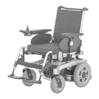
- Page 11 OVERVIEW Model 1.611 The overview shows the most important components and operating devices of the electric wheelchair. Pos. Description (1) Back support (2) Arm support (3) Seat cushion (4) Leg support (5) Calf belt (6) Footplate (7) Steering wheel (8) Driving wheel...
- Page 12 OVERVIEW Model 1.612 The overview shows the most important components and operating devices of the electric wheelchair. Pos. Description (1) Back support (2) Arm support (3) Seat cushion (4) Leg support (5) Calf plate (6) Footplate (7) Steering wheel (8) Driving wheel (9) Shunting rod (10) Operating module (11) Front lighting...
- Page 13 OVERVIEW Model 1.613 The overview shows the most important components and operating devices of the electric wheelchair. Pos. Description (1) Back support (2) Arm support (3) Operating module (4) Front lighting (5) Driving wheel (6) Leg support (7) Support castor (8) Selection lever drive-/push mode (9) Steering wheel (10) Rear lighting...
- Page 14 OVERVIEW Model 1.615 The overview shows the most important components and operating devices of the electric wheelchair. Pos. Description (1) Back support (2) Arm support (3) Operating module (4) Seat cushion (5) Calf belt (6) Footplate (7) Steering wheel (8) Selection lever drive-/push mode (9) Driving wheel (10) Front lighting (11) Shunting rod...
- Page 15 OVERVIEW Model 1.616 The overview shows the most important components and operating devices of the electric wheelchair. Pos. Description (1) Back support (2) Arm support (3) Seat cushion (4) Footplate (5) Steering wheel (6) Driving wheel (7) Shunting rod (8) Operating module (9) Selection lever drive-/push mode (10) Support castor (11) Battery case...
- Page 16 HANDLING THE ELECTRIC BRAKES WHEELCHAIR Service brake Securing the electric wheelchair The motors work electrically as operating brake and carefully brake the electric wheel- The electric wheelchair is to be secured as chair down without jerks to stillstand. follows to prevent it from rolling off unin- tentionally: Braking the wheelchair Switch the selection lever for drive-/...
- Page 17 Locking the brakes To engage the brakes swivel the selection lever drive-/push mode on both sides as far as possible into drive mode [1]. ☞ Activation of the selection lever is in- tended for an accompanying person. Attention: It should not be possible to push the electric wheelchair forward when the brakes are engaged.
- Page 18 Drive-/push mode Attention: Only switch the electric wheelchair to push mode when it is standing still for positioning or in case of emergencies, but not on slopes/hills. ☞ The electric magnetic brakes are switched off in the push mode. – A braking of the electric wheelchair is then only possible by switching to the drive mode.
- Page 19 SELECTING THE OPERATION In order to obtain operational readiness of the electric wheelchair the following direc- tions are to be carried out in the indicated order. ☞ Note: Charge the drive batteries via the oper- ating module before the first journey. Selecting the motor mode Switch the drive motors to the drive mode [1].
- Page 20 Position of the operating module ☞ The operating module should be positioned in such a way that you can comfortably and safely steer the electric wheelchair. ☞ The distance of the operating mod- ule to the padded arm supports can be adjusted after loosening the clamping screw (3).
- Page 21 Pre-operation checks Before starting to drive, the following should be checked: ☞ the battery charging condition, ☞ the setting of the preselected final speed. – For this observe the operating manual < Operating module >. Battery charging procedure ☞ For the battery charging procedure also observe the operating manual of the battery charger.
- Page 22 Positioning the operating module Function description You will find a detailed description of the keys and symbols in the operating manual for < Operating module >. The position of the operating module can be adjusted to suit the individual size of the user.
- Page 23 Swivelling the operating module With the optional swivel away operating module adapter [1] the operating module can be swivelled back to the side (2) so that it is located parallel to the arm support. This makes it possible, for example: –...
- Page 24 LEG SUPPORTS Attention: Before any actions on the leg supports the wheelchair is to be secured against unintentional rolling motions. ☞ Therefore observe chapter Securing the electric wheelchair on page 16. Calf belt The removable calf belt (1) prevents the feet from sliding off the back of the footplates.
- Page 25 Lower leg support For entry or exiting the footplates resp. foot- board is to be folded upward [1] + [2] or the central leg support [2] lowered to the floor. ☞ Check the locking points! – Remove both feet from the footplates. –...
- Page 26 Leg support upper part The upper leg support with an inserted lower leg support is termed leg support. Turning the leg supports to the side For easy transfer out of/into the electric wheelchair as well as driving closer to a closet, bed or bathtub the leg supports can be swivelled away toward the in-/outside [1] and [2].
- Page 27 Swivelling in the leg supports For inward swivelling, let the leg supports swivel forward until the lock audibly engag- es [1]. ☞ Note: After audibly swivelling the leg sup- ports inward check the respective lock- ing device. ☞ Afterwards observe chapter Lower leg support on page 25.
- Page 28 Removing the leg supports For easy transfer into and out of the electric wheelchair as well as a reduced wheelchair length (important for transport) the leg sup- ports can be removed [1]. ☞ Note: Remove the calf belt before swivelling away the leg supports.
- Page 29 Mechanically height-adjustable leg supports Attention: Never put the free hand into the adjust- ment mechanism while adjusting the height adjustable leg support. – Dan- ger of jamming! • Have the leg support that is to be ad- justed secured against falling away by an accompanying person.
- Page 30 Electrically height-adjustable leg support The electrically height adjustable leg sup- port [1]+[2] automatically receives electric contact when hooked on. Attention: Never put the free hand into the adjust- ment mechanism while adjusting the height adjustable leg support. – Dan- ger of jamming! Height adjustment For height adjustment, raise or lower the leg support to the desired height via the oper-...
- Page 31 Removing the electrically height adjust- able leg support In order to remove the leg support, depend- ing on version, first pull the locking lever (1) back, press it in or fold it up or down. Afterwards swivel the leg support sideways and remove it toward the top [2].
- Page 32 ARM SUPPORTS Attention: Do not use the arm supports [1] to lift or carry the electric wheelchair. • Do not drive without the arm supports! Removing the arm support To remove the arm support, loosen the clamping screw (2) first and then pull out the arm support toward the top .
- Page 33 Illuminated clothes guard discs Attention: A selected lighting is still active after switching off the operating module. • Activated lighting may not be used where the German road traffic regula- tions are valid. Activating/deactivating the lighting on the clothes guard discs Activate the switch (1) to switch the lighting on or off.
- Page 34 BACK SUPPORT The back support can be folded down for storage or transport. ☞ Note: For better demonstration of the wire cable (1) the back support is shown without cushion. Folding down the back support – If required remove the seat pad (velcro fastener).
- Page 35 Any change to the seat inclination will on hills/slopes. lead to different safe back support ad- justments! Model 1.610/1.611 Seat inclina- safe position of the back support incli- Adjusted seat inclination tion nation [1] 0°...
- Page 36 Adjustable back The adjustable back is adjustable through a velcro strap on the spanning straps (2). Removing the back support upholstery For removal, first pull off the rear part of the back support upholstery (1), then fold it over to the front and pull it off of the adjustable back strap (3).
- Page 37 Electrically adjustable back support The back support [1] is electrically adjusta- ble. ☞ Note: Herefore view the operating manual < Operating module >. Attention: Only adjust the back support when the electric wheelchair is standing on a level surface. A danger of tipping over exists on gradients! Folding down the electrically adjustable back support...
- Page 38 Back support upholstery The back support upholstery is secured to the back support shell with Velcro fasteners and can be pulled off [1]. Secure positions of the back support The diverse possible seat adjustments also includes such settings, that may only be used as resting positions, since they might lead to instable driving conditions in drive mode.
- Page 39 SEAT Seat pad The seat pad [1] is attached to the seat plate with velcro straps and can be removed for cleaning and maintenance. Replace and attach the seat pad again after cleaning or maintenance [1]. – Velcro fasten- Seat cushion The seat cushion is placed with the burling side onto the seat plate [2].
- Page 40 Manually adjusting the seat angle (only with model 1.613) To adjust the manual seat inclination, open the folding plug (3) and insert it into a differ- ent hole (5)–(8) of the adjustment tube (4). ☞ After repositioning the folding plug, make sure that it is closed correctly.
- Page 41 Seat height adjustment Attention: • Use of the seat height adjustment is only permitted on straight surfaces and during stillstand of the vehicle. The seat height [1] can be adjusted through the operating module. ☞ Through this the seat height can be continuously adjusted up to.
- Page 42 HEAD SUPPORT The head support is swivel/proof, height- and depth adjustable and removable. Attention: We recommend the fitting of two rear- view mirrors for driving with a head support. Adjustment of the head support The head support can be detached or ad- justed in height after the clamping lever (1) has been slackened.
- Page 43 USB CONNECTOR SOCKET The USB connector socket serves to con- nect devices with a USB plug type A. Attention: The maximum power consumption may not exceed 1 A per connection. ☞ The USB connector socket requires a permanent power supply. This may re- quire a more frequent recharging of the batteries.
- Page 44 ATTENDANT CONTROL WITH PRIORITY SWITCH The control unit for accompanying person enables the accompanying person an easy control of the electric wheelchair with auxil- iary operating module. Positioning the controller ☞ Note: Switch off the operating module before position adjustment! – This prevents an unwanted movement of the electric wheelchair.
- Page 45 LIGHTING For driving outdoors and on public roads the electric wheelchair can be fit with LED-lighting equipment. The lighting is activated over the operating module for the driver. ☞ Note: Observe the operating manual < Oper- ating module > as well as the safety and general handling instructions <...
- Page 46 Observe safety and general handling in motor vehicles >! – This document and instructions < Electric vehicles > chapter further information can be accessed on < Ramps and lifting platforms >. our website < www.meyra.com > in the < Download Archive >.
- Page 47 Transport security The electric wheelchair is only to be se- cured through the anchoring positions (1)+(3) resp. (2)+(4). ☞ The procedure for securing the wheel- chair can be read in the document < Safety and general handling instruc- tions electric vehicles > chapter < Trans- port in motor vehicles or with conveyors >.
- Page 48 Maintenance schedule WHEN WHAT REMARK Before starting out General Carry out test yourself or with a helper. Test for faultless operation. Checking the magnet- Carry out test yourself or with ic brake a helper. Move the selection lever If the electric wheelchair can for the drive/push mode be pushed, have the brakes into the drive mode posi-...
- Page 49 WHEN WHAT REMARK Every 2 months Check tyre profile Carry out a visual check your- (depending on dis- self or with a helper. Minimum tread = 1 mm tance covered) If the tyre profile is worn down or if the tyre is dam- aged, consult a specialist workshop for repairs.
- Page 50 Fuses Replacing the fuses Before replacing fuses, park the electric wheelchair on a level surface and secure it from rolling away. ☞ Therefore observe chapter Securing the electric wheelchair on page 16. Attention: Only replace the safety fuse with a safe- ty fuse of the same type! New fuses can be obtained for example at petrol stations.
- Page 51 Lighting The lighting (1)+(2) is equipped with longlife LED-technology. ☞ Note: If a turn-signal bulb is defective, the re- maining one blinks at double frequen- ☞ Immediately have a defective LED-lamp repaired by a specialist workshop. Headlights The housing of the light (1) must be adjust- ed so that the light cone is visible on the driving surface.
- Page 52 Fault correction Fault Cause Remedy Battery indicator on the Battery fuse is defective or Replace defective fuse or operating module does not correctly inserted. clean contacts and insert not light up after the correctly. switch-on. Plug connection of the Check the plug connec- power supply without...
- Page 53 SERVICE ☞ Do not soak! Do not machine wash! Follow-up with clean water and allow to dry. Tyres Plastic parts The following items need to be checked: The plastic panelling is attacked through – the air pressure (only on pneumatic non-ionic tensides as well as solvents and tyres) especially alcohol.
- Page 54 Disinfection Repairs If the product is used by more than one per- Trustfully contact your local specialist dealer son (for example in a care centre), the use of of another specialist workshop for carrying a commercial disinfectant is mandatory. out repairs. They are briefed in carrying out the work and have educated personnel.
- Page 55 Disposal The disposal must comply with the respec- tive national law. Please enquire about local disposal arrange- ments at your municipal authority. The vehicle packing material can be dis- posed of as recyclable material. The metal parts can be disposed of as recy- clable scrap metal.
- Page 56 TECHNICAL DATA – reduced driving speed (especially at walking speed). Maximum range In practical use, the maximum range under 'normal conditions' is then reduced to ap- The maximum range depends to a large ex- prox. 80 – 40 % of the nominal value. tent on the following factors: –...
- Page 57 Values acc. to ISO 7176-15 for model 1.610 Overall length with leg support 1080 mm – mm Overall width 580 mm 750 mm Overall dimensions – kg 220 kg User weight (incl. additional load) – kg 120 kg Weight of the heaviest part 4.5 kg –...
- Page 58 Further technical data for model 1.610 Sound level < 70 dB(A) Protection class IP X4 Turning area 1300 mm Drive controller 24 V / 60 A 24 V / 90 A Engine output (6 / 10 km/h) 180 W Main fuse 80 A Lighting (option) LED-technology 24 V...
- Page 59 Steering wheel 230 x 70 mm (9“) puncture proof / puncture safe 260 x 70 mm (10“) puncture proof / puncture safe Driving wheel 320 x 75 mm (12.5“) puncture proof / puncture safe 356 x 75 mm (14“) puncture proof / puncture safe Drive batteries 2 x 12 V 63 Ah (5 h) / 73 Ah (20 h) sealed, maintenance free...
- Page 60 Values acc. to ISO 7176-15 for model 1.611 Overall length with leg support 1130 mm – mm Overall width 580 mm 800 mm Overall dimensions – kg 320 kg User weight (incl. additional load) – kg 160 kg User weight (incl. additional load) with seatlift –...
- Page 61 Further technical data for model 1.611 Lifting height Seatlift 300 mm Sound level < 70 dB(A) Protection class IP X4 Turning area 1300 mm Drive controller 24 V / 70 A 24 V / 120 A Engine output (6 / 10 km/h)
- Page 62 Steering wheel 230 x 70 mm (9“) puncture proof / puncture safe 260 x 70 mm (10“) puncture proof / puncture safe Driving wheel 320 x 75 mm (12.5“) puncture proof / puncture safe 356 x 75 mm (14“) puncture proof / puncture safe Drive batteries 2 x 12 V 63 Ah (5 h) / 73 Ah (20 h) sealed, maintenance free...
- Page 63 Values acc. to ISO 7176-15 for model 1.612 Overall length with leg support 1120 mm – mm Overall width 630 mm 800 mm Overall dimensions – kg 320 kg User weight (incl. additional load) – kg 160 kg User weight (incl. additional load) with seatlift –...
- Page 64 Further technical data for model 1.612 Lifting height Seatlift 300 mm Sound level < 70 dB(A) Protection class IP X4 Turning area 1350 mm Drive controller 24 V / 70 A 24 V / 120 A Engine output (6 / 10 km/h) 220 W 350 W Main fuse...
- Page 65 Steering wheel 260 x 70 mm (10“) puncture proof / puncture safe Driving wheel 356 x 75 mm (14“) puncture proof / puncture safe Drive batteries 2 x 12 V 63 Ah (5 h) / 73 Ah (20 h) sealed, maintenance free Max.
- Page 66 Values acc. to ISO 7176-15 for model 1.613 Overall length with leg support 1065 mm 1130 mm Overall width 620 mm 800 mm Overall dimensions – kg 280 kg User weight (incl. additional load) – kg 160 kg User weight (incl. additional load) with seatlift –...
- Page 67 Further technical data for model 1.613 Lifting height Seatlift 300 mm Sound level < 70 dB(A) Protection class IP X4 Turning area 1150 mm Drive controller 24 V / 70 A 24 V / 90 A Engine output (6 / 10 km/h) 220 W 300 W Main fuse...
- Page 68 Steering wheel 230 x 70 mm (9“) puncture proof / puncture safe Driving wheel 356 x 75 mm (14“) puncture proof / puncture safe Drive batteries 2 x 12 V 63 Ah (5 h) / 73 Ah (20 h) sealed, maintenance free Max.
- Page 69 Values acc. to ISO 7176-15 for model 1.615 Overall length with leg support 1080 mm – mm Overall width 650 mm 800 mm Overall dimensions – kg 280 kg User weight (incl. additional load) – kg 160 kg Weight of the heaviest part 4.5 kg –...
- Page 70 Further technical data for model 1.615 Sound level < 70 dB(A) Protection class IP X4 Turning area 1300 mm Drive controller 24 V / 70 A 24 V / 120 A Engine output (6 / 13 km/h) 220 W 300 W Main fuse 80 A Lighting (option)
- Page 71 Steering wheel 260 x 70 mm (10“) puncture proof / puncture safe Driving wheel 380 x 75 mm (15“) puncture proof / puncture safe Drive batteries 2 x 12 V 63 Ah (5 h) / 73 Ah (20 h) sealed, maintenance free Max.
- Page 72 Values acc. to ISO 7176-15 for model 1.616 Overall length with leg support 970 mm – mm Overall width 580 mm 800 mm Overall dimensions 200 kg 280 kg User weight (incl. additional load) – kg 75 kg Weight of the heaviest part 1.6 kg –...
- Page 73 Further technical data for model 1.616 Sound level < 70 dB(A) Protection class IP X4 Turning area 1300 mm Drive controller 24 V / 70 A 24 V / 90 A Engine output (6 / 13 km/h) 180 W 300 W Main fuse 80 A Lighting (option)
- Page 74 Steering wheel 190 x 50 mm (8“) puncture proof / puncture safe 230 x 70 mm (9“) puncture proof / puncture safe Driving wheel 320 x 60 mm (12.5“) puncture proof / puncture safe Drive batteries 2 x 12 V 63 Ah (5 h) / 73 Ah (20 h) sealed, maintenance free Max.
- Page 75 Meaning of the labels on the electric wheelchair Attention! Read the operating manuals and other provided documen- tation. Do not lift the electric wheelchair at the arm supports or leg supports. Removable parts are not suitable for carrying. Drive mode Push mode Push only on level surfaces.
- Page 76 Meaning of the symbols on the type plate Manufacturer Order number Serial number Production date (Year – Calendar week) Permitted user weight max. permissible total weight Permitted axle weights Max. permissible rising gradient Max. permissible falling gradient Permitted maximum speed The product is approved as a seat within a motor vehicle The product is not approved as a seat within a motor vehicle.
- Page 77 Meaning of the symbols on the washing instruction (the symbols correspond to European standard) Gentle cycle with the indicated temperature in °C Not suited for the dryer Do not iron Do not use chlorine bleach No dry-cleaning possible Meaning of symbols on the label Seatlift (only with model 1.613) Seat depth perm.
- Page 78 INSPECTION CERTIFICATE Recommended safety inspection 1st year (at least every 12 months) Vehicle data: Stamp of specialist dealer: Model: Signature: Delivery note no.: Place, date: Serial-no.(SN): Next safety inspection in 12 months Date: Recommended safety inspection 2nd year Recommended safety inspection 3rd year (at least every 12 months) (at least every 12 months) Stamp of specialist dealer:...
- Page 79 WARRANTY / GUARANTEE Interferences through radiation sources such as mobile phones with high trans- mission power, HiFi-equipment and other We accept legal liability for this product extreme interference radiators outside of within the scope of or general terms and norm specifications cannot be declared as conditions and warranty and in certain cas- warranty or guarantee claims.
- Page 80 Warrantee / Guarantee section Please fill out! Copy if necessary and send the copy to the specialist dealer. Warranty / Guarantee Model designation: Delivery note no.: SN (view type plate): Date of delivery: Stamp of the specialist dealer: Inspection certificate for transfer Vehicle data: Serial-no.(SN): Stamp of specialist dealer:...
- Page 81 NOTES...
- Page 82 NOTES...
- Page 83 NOTES...
- Page 84 Your specialist dealer MEYRA GmbH Meyra-Ring 2 32689 Kalletal Kalldorf GERMANY +49 5733 922 - 311 +49 5733 922 - 9311 info@meyra.de www.meyra.de 205 338 101 (Status: 2018-05) All technical modifications reserved. Original operating manual.
Need help?
Do you have a question about the 1.611 and is the answer not in the manual?
Questions and answers