Table of Contents
Advertisement
Quick Links
Advertisement
Table of Contents

Related Manuals for Meyra 1.618


Summary of Contents for Meyra 1.618
- Page 1 Electric wheelchair Model 1.618 Operating manual W e m o v e p e o p l e .
-
Page 2: Table Of Contents
Contents Meaning of the applied markers Introduction List of models Indications Acceptance Specifications Adjustment Reinstallment Life span Statutory regulations High-frequency radiation Overview Model1.618 Handling the electric wheelchair Securing the electric wheelchair Functional checks Driving Brakes Service brake Braking the wheelchair Parking brake Locking the brakes Releasing the brakes... - Page 3 Selecting the operation Pre-operation checks Battery charging procedure Positioning the operating module Function description Adjusting the distance to the padded arm support Removing the operating module Inserting the operating module Swivelling the operating module Height adjustment of the operating module Leg supports Central leg support Calf belt...
- Page 4 Back support Folding down the back support Unfolding the back support Secure positions of the back support Adjustable back Removing the back support upholstery Placing the back support upholstery Electrically adjustable back support Folding down the electrically adjustable back support Unfolding the back support Back support upholstery Tilt switch (optional)
- Page 5 Technical data Maximum range Applied norms Hill climbing ability Values acc. to ISO 7176-15 for model 1.618 Further technical data for model 1.618 Meaning of the labels on the electric wheelchair Meaning of the symbols on the type plate Meaning of the symbols on the washing instruction...
-
Page 6: Meaning Of The Applied Markers
Users with visual impairments can find the PDF-files together with further information on our website: < www.meyra.com >. ☞ Contact your specialist dealer when re- quired. Information about product safety, possible recalls and general handling instructions of our products can be found in the <... -
Page 7: Acceptance
ACCEPTANCE All products are checked for faults in the Do not reach onto the turning surface of factory and packed in special boxes. the wheels or grip the tyres of the rotating ☞ However, we request that you check wheels. – Danger of injury! the vehicle for possible transport dam- The wheelchair is driven through the joy- age immediately on receipt –... -
Page 8: Adjustment
ADJUSTMENT REINSTALLMENT The wheelchair is suited for reinstallment. Always have adaptation and adjustment With the building block system the wheel- work carried out by a specialist dealer. chair can be fit to accommodate different The wheelchair offers manifold adjustment handicaps body sizes. Before reimplemen- possibilities to individual vital statistics. -
Page 9: Statutory Regulations
STATUTORY HIGH-FREQUENCY REGULATIONS RADIATION Please comply with the legal requirements Our electric vehicles are conform with the of the country in which the wheelchair is corresponding requirements of the EG-di- used. rective 93/42 EWG for medical devices. Nev- ertheless Interferences from high frequency ☞... -
Page 10: Overview
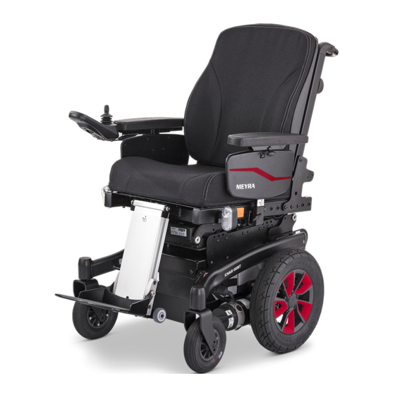
OVERVIEW Model1.618 The overview shows the most important components and operating devices of the electric wheelchair. Pos. Description (1) Head support (2) Back support (3) Arm support (4) Seat cushion (5) Steering wheel fork (6) Footplate (7) Steering wheel (8) Type plate (9) Selection lever drive-/push mode (10) Driving wheel (11) Pushing bar... -
Page 11: Handling The Electric Wheelchair
HANDLING THE ELECTRIC BRAKES WHEELCHAIR Brake the vehicle down carefully and in time. This is especially the case when driv- Only transfer into or out of the electric ing in front of people and while driving wheelchair when the electric wheelchair downhill! is switched off and the selection lever Service brake... -
Page 12: Locking The Brakes
Locking the brakes It should not be possible to push the elec- tric wheelchair forward when the brakes are engaged. To engage the brakes swivel the selection lever drive-/push mode on both sides as far as possible into drive mode [1]. ☞... -
Page 13: Drive-/Push Mode
Drive-/push mode Only switch the electric wheelchair to push mode when it is standing still for positioning or in case of emergencies, but not on slopes/hills. After push mode do not forget to switch the drive back to drive mode. Danger of uncontrolled electric wheelchair move- ment if you do not do this. -
Page 14: Selecting The Operation
SELECTING THE OPERATION In order to obtain operational readiness of the electric wheelchair the following direc- tions are to be carried out in the indicated order. ☞ Charge the drive batteries via the oper- ating module before the first journey. Selecting the motor mode. - Page 15 Check the position of the operating module. The operating module should be posi- tioned in such a way that you can comfort- ably and safely steer the electric wheelchair. Adjusting the distance to the padded arm support: After the adjustment retighten the clamp- ing screw.
-
Page 16: Pre-Operation Checks
Pre-operation checks Before starting to drive, the following should be checked: ☞ the battery charging condition. ☞ the setting of the preselected final speed. – For this observe the operating manual < Operating module >. Battery charging procedure Do not insert any objects other than the battery charger plug into the battery charging socket. -
Page 17: Positioning The Operating Module
Positioning the operating module Switch off the operating module before adjusting/removing it. Function description You will find a detailed description of the keys and symbols in the operating manual for < Operating module >. The position of the operating module can be adjusted to suit the individual size of the user. -
Page 18: Swivelling The Operating Module
Swivelling the operating module Do not grab into the area of the cross brace. – Danger of squashing! With the swivel away operating module adapter [1] the operating module can be swivelled back to the side (2) so that it is located parallel to the arm support. -
Page 19: Leg Supports
LEG SUPPORTS Before any actions on the leg support the electric wheelchair is to be secured against unintentional rolling motions. ☞ Therefore observe chapter Securing the electric wheelchair on page 11. Central leg support The footboard [1] can be folded upward [2] in order to ease entry or exiting of the user. -
Page 20: Calf Belt
Calf belt Do not drive without the calf belt. – Dan- ger of accident! The removable calf belt (1) prevents the feet from sliding off the back of the footplates. ☞ The calf belt must be removed in order to swivel away the leg supports. ☞... -
Page 21: Lower Leg Support
Lower leg support The footplates, resp. footboard needs to be folded up before entry or exit [1] / [2]. ☞ Check the locking points! – Remove both feet from the footplates. – Remove the calf belt (3), if present. ☞ Therefore observe chapter Calf belt on page 20. -
Page 22: Leg Support Upper Part
Leg support upper part The upper leg support with an inserted lower leg support is termed leg support. Turning the leg supports to the side Leg supports turned to the side are re- leased automatically and can easily come off. For easy transfer out of/into the electric wheelchair as well as driving closer to a clos- et, bed or bathtub the leg supports can be... - Page 23 Swivelling in the leg supports For inward swivelling, let the leg supports swivel forward until the lock audibly engag- es [1]. ☞ After audibly swivelling the leg sup- ports inward check the respective lock- ing device. ☞ Afterwards observe chapter Lower leg support on page 21.
-
Page 24: Swivelling In The Leg Supports
Removing the leg supports For easy transfer into and out of the electric wheelchair as well as a reduced wheelchair length (important for transport) the leg sup- ports can be removed [1]. ☞ Remove the calf belt before swivelling away the leg supports. ☞... -
Page 25: Mechanically Height-Adjustable Leg Supports
Mechanically height-adjustable leg supports Never put the free hand into the adjust- ment mechanism while adjusting the height adjustable leg support. – Danger of jamming! Have the leg support that is to be adjust- ed secured against falling away by an ac- companying person. -
Page 26: Electrically Height-Adjustable Leg Support
Electrically height-adjustable leg support Never put the free hand into the adjust- ment mechanism while adjusting the height adjustable leg support. – Danger of jamming! Electric contact is automatically established when attaching the electrically height ad- justable leg support [1]. Height adjustment For height adjustment, raise or lower the leg support to the desired height via the oper-... -
Page 27: Removing The Electrically Height Adjustable Leg Support
Removing the electrically height adjust- able leg support When the electrically height adjustable leg supports are removed the electric contact (3) needs to be protected from dampness, water and dust or dirt (e. g. for longer storage)! ☞ Possible function error of the electri- cal adjustment. -
Page 28: Arm Supports
ARM SUPPORTS Do not use the arm supports [1] to lift or carry the electric wheelchair. Do not drive without the arm supports! Removing the arm support To remove the arm support, loosen the clamping screw (2) first and then pull out the arm support toward the top . -
Page 29: Back Support
BACK SUPPORT The back support can be folded down for storage or transport. ☞ For better demonstration of the wire cable (1) the back support is shown without cushion. Folding down the back support ☞ If required remove the seat pad (velcro fastener). -
Page 30: Adjustable Back
Adjustable back The adjustable back is adjustable through a velcro strap on the spanning straps (2). Removing the back support upholstery For removal, first pull off the rear part of the back support upholstery (1), then fold it over to the front and pull it off of the adjustable back strap (3). -
Page 31: Electrically Adjustable Back Support
Electrically adjustable back support Any change to the seat inclination will lead to different safe back support adjust- ments! Only adjust the back support when the electric wheelchair is standing on a level surface. A danger of tipping over exists on gradients! The back support [1] is electrically adjusta- ble. -
Page 32: Back Support Upholstery
Back support upholstery The back support upholstery is secured to the back support shell with Velcro fasteners and can be pulled off [1]. Tilt switch (optional) Optionally your electric wheelchair can be equipped with a tilt switch that limits the back support angle in combination with the seat inclination. -
Page 33: Seat
SEAT Seat pad The seat pad [1] is attached to the seat plate with velcro straps and can be removed for cleaning and maintenance. Replace and attach the seat pad again after cleaning or maintenance [1]. – Velcro fasten- Seat cushion The seat cushion is placed with the burling side onto the seat plate. -
Page 34: Seat Height Adjustment
Seat height adjustment Before seat height adjustment, check whether the adjustment area is free of ob- stacles. – Danger of injury! Use of the seat height adjustment is only permitted on straight surfaces and during stillstand of the vehicle. The seat height [1] can be controlled through the operating module. -
Page 35: Head Support
HEAD SUPPORT We recommend the fitting of two rear- view mirrors for driving with a head sup- port. The head support is swivel/proof, height- and depth adjustable and removable. Adjustment of the head support The maximum height adjustment is indi- cated by the marking! The head support can be detached or ad- justed in height after the clamping lever (1) -
Page 36: Retaining Strap
RETAINING STRAP Make sure that no objects are trapped between belt and the body! – Thus you avoid painful pressure points. The retrospective assembly of a retaining strap is only to be carried out by a special- ist workshop! The retaining strap is not part of the re- taining system for the electric wheelchair and/or the user during transport in motor vehicles. -
Page 37: Usb Connector Socket
USB CONNECTOR SOCKET The maximum power consumption may not exceed 1 A per connection! ☞ The USB connector socket requires a permanent power supply. This may re- quire a more frequent recharging of the batteries. The USB connector socket serves to con- nect devices with a USB plug type A. -
Page 38: Attendant Control With Priority Switch
ATTENDANT CONTROL WITH PRIORITY SWITCH The control unit for accompanying person enables the accompanying person an easy control of the electric wheelchair with auxil- iary operating module. Positioning the controller ☞ Switch off the operating module before position adjustment! – This prevents an unwanted movement of the electric wheelchair. -
Page 39: Rear-View Mirror
REAR-VIEW MIRROR Removing the rear-view mirror To remove the rear-view mirror loosen the clamping screw (2) and pull the rear-view mirror forward out of the arm support tube. ☞ Carefully place the rear-view mirror down and protect the mirror glass from strain or other objects. -
Page 40: Lighting
LIGHTING For driving outdoors and on public roads the electric wheelchair is equipped with LED-lighting equipment. The lighting is activated over the operating module for the driver. ☞ Therefore observe operation manual < Operating module >. ☞ Always switch on the lighting system in poor visibility conditions and especially during darkness in order to see better and be better seen by others. -
Page 41: Transport Of People Inside A Motor Vehicle
>. – This document and further informa- tion are available in the < Information center > on our website < www.meyra. com >. MAINTENANCE An incorrect or neglected cleaning and maintenance results in a limitation of the product liability. -
Page 42: Maintenance Schedule
Maintenance schedule WHEN WHAT REMARK Before starting out General Carry out test yourself or with a helper. Test for faultless operation. Checking the magnet- Carry out test yourself or with ic brake a helper. Move the selection lever If the electric wheelchair can for the drive/push mode be pushed, have the brakes into the drive mode posi-... - Page 43 WHEN WHAT REMARK Every 2 months Check tyre profile Carry out a visual check your- (depending dis- self or with a helper. Minimum tread = 1 mm tance covered) If the tyre profile is worn down or if the tyre is damaged, con- sult a specialist workshop for repairs.
-
Page 44: Fuses
Fuses Only replace the safety fuse with a safety fuse of the same type! Replacing the fuses Before replacing fuses, park the electric wheelchair on a level surface and secure it from rolling away. ☞ Therefore observe chapter Securing the electric wheelchair on page 11. -
Page 45: Lighting
Lighting The lighting (1)+(2) is equipped with longlife LED-technology. ☞ Immediately have a defective LED-lamp repaired by a specialist workshop. Headlights The housing of the light (1) must be adjust- ed so that the light cone is visible on the driving surface. -
Page 46: Fault Correction
Fault correction Fault Cause Remedy Battery indicator on the Battery fuse is defective or Replace defective fuse or operating module does not correctly inserted. clean contacts and insert not light up after the correctly. switch-on. Plug connection of the Check the plug connec- power supply without... -
Page 47: Service
SERVICE ☞ Remove spots with a sponge or a soft brush. – Wash off persistent dirt with com- Tyres mercial fine detergent. The following items need to be checked: ☞ Do not soak! Do not machine wash! – the air pressure (only on pneumatic tyres) Follow-up with clean water and allow to dry. -
Page 48: Disinfection
Disinfection Reinstallment Before reimplementation the electric wheel- If the product is used by more than one per- chair is to undergo a complete inspection. son (for example in a care centre), the use of a commercial disinfectant is mandatory. ☞ The hygienic measures required for reinstallment are to be carried out in Before disinfection the upholstery and han- correspondence with the validated hy-... -
Page 49: Spare Parts
Spare parts Disposal Safety relevant parts or assembly groups are only to be assembled in a specialist workshop. – Danger of accidents! Spare parts can only be ordered from spe- cialist dealers. In case of repair work, only original spare parts are to be used! ☞... -
Page 50: Information For The Specialist Dealer
A maintenance and service manual for ming device. this wheelchair is available on our website < www.meyra.com > in the service area ☞ Therefore observe respective < Download >, in which you can find the fol- <... -
Page 51: Technical Data
TECHNICAL DATA Calculation of the max. user weight: The maximum total load is calculated on Maximum range the basis of the unloaded weight of the wheelchair and the maximum passenger The maximum range depends to a large ex- weight. tent on the following factors: Additional weight due to subsequent addi- –... -
Page 52: Values Acc. To Iso 7176-15 For Model 1.618
Values acc. to ISO 7176-15 for model 1.618 min. max. Overall length (measured at 4° seat inclination) with central leg support 1060 mm 1150 mm with divided leg supports 1180 mm 1250 mm Overall width 12"-wheel / 14"-wheel SW = 380 mm... - Page 53 min. max. Seat lift, code 27: Seat lift (lifting height) 0 mm 300 mm Seat angle 0° 30° Seat surface height 870 mm (with Ergoseat with extended seat lift) Back support angle, mechanical -10° 30° (Measured to vertical on the seat plate) Back support angle, electrical -10°...
- Page 54 min. max. Minimal turning radius (measured at 4° seat inclination) with central leg supports 700 mm 800 mm (depending on features) with divided leg supports 800 mm 900 mm (depending on features) Weight of the dummy (ISO 7176-8) 76 kg Max.
-
Page 55: Further Technical Data For Model 1.618
Further technical data for model 1.618 min. max. Sound level 70 dB(A) Protection class IP X4 Min. turning area central leg support 1050 mm 1150 mm divided leg support 1130 mm 1230 mm Performance drive control with 180 W 24 V / 70 A... - Page 56 min. max. Height, with standard- or adjustable back 630 mm 710 mm Height, with ErgoSeat-cushion 700 mm 800 mm (Without arm support, back folded onto seat, seat cushion removed from seat plate and laid onto back) Climatic data Ambient temperature -25 °C to +50 °C Storage temperature with drive batteries -25 °C to +50 °C...
-
Page 57: Meaning Of The Labels On The Electric Wheelchair
Meaning of the labels on the electric wheelchair Attention! Read the operating manuals and other provided documen- tation. Do not lift the electric wheelchair at the arm supports or leg supports. Removable parts are not suitable for carrying. Drive mode Push mode Push only on level surfaces. -
Page 58: Meaning Of The Symbols On The Type Plate
Meaning of the symbols on the type plate Manufacturer Order number Serial number Production date Permitted user weight max. permissible total weight Permitted axle weights Max. permissible rising gradient Max. permissible falling gradient Permitted maximum speed The product is approved as a seat within a motor vehicle Max. -
Page 59: Meaning Of The Symbols On The Washing Instruction
Meaning of the symbols on the washing instruction (the symbols correspond to European standard) Gentle cycle with the indicated temperature in °C Not suited for the dryer Do not iron Do not use chlorine bleach No dry-cleaning possible... -
Page 60: Inspection Certificate
INSPECTION CERTIFICATE Recommended safety inspection 1st year (at least every 12 months) Vehicle data: Stamp of specialist dealer: Model: Signature: Delivery note no.: Place, date: Serial-no.(SN): Next safety inspection in 12 months Date: Recommended safety inspection 3rd year Recommended safety inspection 2nd year (at least every 12 months) (at least every 12 months) Stamp of specialist dealer:... -
Page 61: Warranty / Guarantee
WARRANTY / GUARANTEE Attention: Failure to observe the instructions in the operating manual, improperly car- We accept legal liability for this product ried out maintenance work and, espe- within the scope of or general terms and cially, technical changes and additions conditions and warranty and in certain cas- (add-ons) carried out without our prior es other verbal resp. -
Page 62: Warrantee / Guarantee Section
Warrantee / Guarantee section Please fill out! Copy if necessary and send the copy to the specialist dealer. Warranty / Guarantee Model designation: Delivery note no.: SN (view type plate): Date of delivery: Stamp of the specialist dealer: Inspection certificate for transfer Vehicle data: Serial-no.(SN): Stamp of specialist dealer:... -
Page 63: Notes
NOTES... - Page 64 Your specialist dealer MEYRA GmbH Meyra-Ring 2 32689 Kalletal Kalldorf GERMANY +49 5733 922 - 311 +49 5733 922 - 9311 info@meyra.de www.meyra.de 205 346 601 (Status: 2019-01) All technical modifications reserved. Original operating manual.
Need help?
Do you have a question about the 1.618 and is the answer not in the manual?
Questions and answers