Fronius Smart Meter IP Operating Instructions Manual
Hide thumbs
Also See for Smart Meter IP:
- Quick start manual (4 pages) ,
- Operating instructions manual (60 pages)

Related Manuals for Fronius Smart Meter IP


Summary of Contents for Fronius Smart Meter IP
- Page 1 Operating Instructions Fronius Smart Meter IP Operating Instructions 42,0426,0464,EN 003-11052023...
-
Page 3: Table Of Contents
Terminating resistors Setting the Modbus RTU BIAS Start-up Commissioning the Fronius Smart Meter IP Commissioning the Fronius Smart Meter IP with smartphone or tablet Commissioning the Fronius Smart Meter IP with PC Fronius SnapINverter General Connecting to the Fronius Datamanager... - Page 4 Configuring the Fronius Smart Meter IP as a secondary meter Modbus participants - Fronius GEN24 Multi-meter system - Explanation of symbols Multi-meter system - Fronius GEN24 inverter Fronius Smart Meter IP - website Overview Overview Settings Advanced settings Performing a factory reset...
-
Page 5: Safety Rules
Safety rules... -
Page 7: Safety Rules
Safety rules Explanation of DANGER! safety notices Indicates immediate danger. ▶ If not avoided, death or serious injury will result. WARNING! Indicates a potentially hazardous situation. ▶ If not avoided, death or serious injury may result. CAUTION! Indicates a situation where damage or injury could occur. ▶... -
Page 8: Environmental Conditions
Any safety devices that are not fully functional must be repaired by an author- ised specialist before the device is switched on. Never bypass or disable protection devices. For the location of the safety and danger notices on the device, refer to the sec- tion headed "General remarks"... -
Page 9: General Information
General information... -
Page 11: Fronius Smart Meter Ip
RCM mark – tested in accordance with the requirements of Australia and New Zealand. Intended use The Fronius Smart Meter IP is a fixed piece of equipment for public grids of TN/TT systems and records self-consumption and/or individual loads in the sys-... -
Page 12: Scope Of Supply
The installation is carried out on an indoor DIN rail with corresponding back-up fuses, which are adapted to the cable cross-sections of the copper conductors and to the maximum current of the meter. The Fronius Smart Meter IP must only be operated in accordance with the specifications in the enclosed documentation and in accordance with local laws, regulations, provisions, standards and within the limits of technical possibilities. -
Page 13: Measuring Accuracy
Technical data on page 50. Backup power The Fronius Smart Meter IP is backup power capable with Modbus RTU / TCP mode data cabling. When connecting via Modbus TCP, make sure that the grid reset time is increased by starting the network. Fronius recommends a Modbus RTU... -
Page 14: Control Elements, Connections And Displays
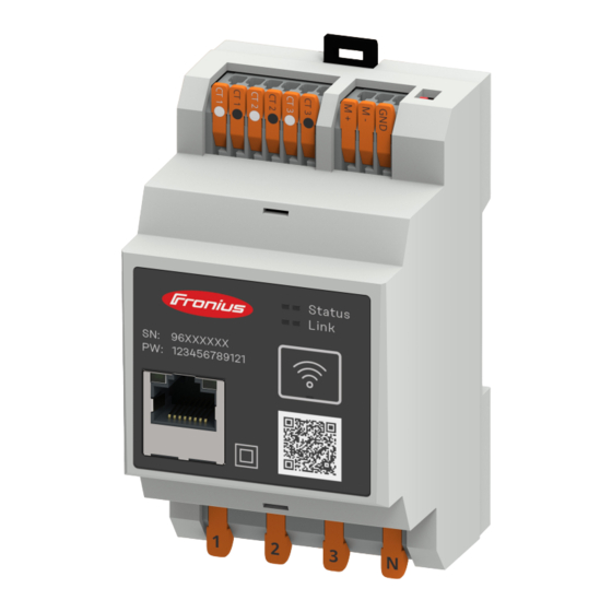
QR code AC connection area LED status indic- The LED status indicator shows the operating status and data connection of the ator Fronius Smart Meter IP. Status 1 LED Lights up green: Ready Link 1 LED Lights up green: Data connec- tion established with the net- work. -
Page 15: Installation
Installation... -
Page 17: Preparations
Preparations Selecting the Please note the following criteria when choosing a location for the Smart Meter: Smart Meter loc- ation Only install on a solid, non-flammable surface. Max. ambient temperatures: -25 °C – +55 °C Relative humidity: max. 93% When installing the Smart Meter in a switch cabinet or similar closed environ- ment, it is necessary to make sure that the hot air that develops will be dissip- ated by forced-air ventilation. -
Page 18: Installation
(see Connecting the current transformers on page 21). Establish the data connection of the Fronius Smart Meter IP. The data con- nection can be established in three different ways: Modbus RTU (recommended if backup power operation is used), see 22, on page 22. -
Page 19: Installation
(circuit breaker, switch or disconnector) and overcurrent protection (auto- matic circuit breaker). The Fronius Smart Meter IP consumes 30 mA, the nominal capacity of the dis- connecting devices and the overcurrent protection is determined by the wire thickness, the mains voltage and the required breaking capacity. -
Page 20: Current Transformer Connection Requirements
2 phases, 3 conductors (CT connection) Current trans- The current transformer must generate 333 mV at nominal current. The nominal former connec- currents of the current transformers are listed in the current transformer data tion require- sheets (Fronius CT, 41,0010,0104 / 41,0010,0105 / 41,0010,0232). ments... -
Page 21: Connecting The Current Transformers
Attach the current transformers to the conductors to be measured and connect the current transformer cables to the Fronius Smart Meter. Switch off the cur- rent before disconnecting the live conductor. Route the mains conductors through the current transformers as described in the previous section. -
Page 22: Connecting The Lan
Modbus RTU the Modbus interface of the Fronius inverter using a network cable (type CAT5 or higher). The Fronius Smart Meter IP can also be connected to the network (LAN / WLAN). This enables software updates to be carried out. -
Page 23: Terminating Resistors - Explanation Of Symbols
Two wires can be installed in each terminal; the wires are twisted first, inser- ted into the terminal and tightened. Note: A loose wire can disable an entire area of the network. The data communication connections of the Fronius Smart Meter IP are electrically isolated from hazardous voltages. Terminating res-... -
Page 24: Setting The Modbus Rtu Terminating Resistor
R 120 Ohm Setting the Mod- The terminating resistor is integrated bus RTU termin- in the Fronius Smart Meter IP and is ating resistor set by a switch. For information on whether the ter- minating resistor must be set or not,... -
Page 25: Setting The Modbus Rtu Bias
OPTION 2 1 = ON 0 = OFF Manufacturer manual Manufacturer manual 0 0 1 max. 300 m OPTION 3 1 = ON 0 = OFF Manufacturer manual Manufacturer manual e. g. Ohmpilot, Battery Inverter Smart Meter 0 0 1 max. - Page 26 Battery Battery...
-
Page 27: Start-Up
Start-up... -
Page 29: Commissioning The Fronius Smart Meter Ip
In the browser address bar, enter and confirm the IP address 192.168.250.181. The installation wizard is opened. Follow the installation wizard in the individual sections and complete the in- stallation. Add the Smart Meter IP in the inverter UI (see Commissioning GEN24 / SnapINverter) Commissioning the Fronius... -
Page 30: Fronius Snapinverter
The Fronius Smart Meter IP can only communicate with Fronius SnapINverter inverters via Modbus RTU. The Fronius Smart Meter IP can also be connected to the network (LAN / WLAN). This enables software updates to be carried out. -
Page 31: Configuring The Fronius Smart Meter Ip As A Secondary Meter
PV modules, self- consumption, the energy fed into the grid and the battery charge (if available). Configuring the Log in to the Smart Meter IP (IP WLAN: 192.168.250.181) and change the Fronius Smart Modbus address accordingly under Advanced Settings >... -
Page 32: Multi-Meter System - Explanation Of Symbols
Primary meter Records the system's load curve and provides measurement data for energy profiling in Fronius Solar.web. The primary meter also controls the dynamic feed-in control. Secondary meter Records the load curve of individual loads (e.g. washing machine, lamps, TV, heat pump, etc.) in the consumption branch and... -
Page 33: Multi-Meter System - Fronius Snapinverter
Terminating resistor R 120 Ohm Multi-meter sys- If several Fronius Smart Meters are installed, a separate address must be set for tem - Fronius Advanced settings on page 44). The primary meter is always as-... - Page 34 Location of the primary meter at the feed-in point. *Terminating resistor R 120 Ohm The following must be observed in a multi-meter system: Only assign each Modbus address once. Terminating resistors must be positioned individually for each channel.
-
Page 35: Fronius Gen24 Inverter
A primary meter and several secondary meters can be selected. The primary meter needs to be configured first before a secondary meter can be selected. The Fronius Smart Meter IP can be connected with Modbus TCP or Modbus RTU. Installation us-... -
Page 36: Configuring The Fronius Smart Meter Ip As The Primary Meter
Smart Meter IP, see Positioning on page 12. If using Fronius Smart Meter (TCP), enter the IP address of the Fronius Smart Meter IP. A static IP address is recommended for the Fronius Smart Meter. Click the button. Click the Save button to save the settings. -
Page 37: Modbus Participants - Fronius Gen24
Click the Save button to save the settings. The Fronius Smart Meter IP is configured as a secondary meter. Modbus parti- Modbus RTU: The inputs M0 and M1 can be selected for this purpose. A maxim- cipants - Fronius... -
Page 38: Multi-Meter System - Explanation Of Symbols
Primary meter Records the system's load curve and provides measurement data for energy profiling in Fronius Solar.web. The primary meter also controls the dynamic feed-in control. Secondary meter Records the load curve of individual loads (e.g. washing machine, lamps, TV, heat pump, etc.) in the consumption branch and... -
Page 39: Multi-Meter System - Fronius Gen24 Inverter
Terminating resistor R 120 Ohm Multi-meter sys- If several Fronius Smart Meters are installed, a separate address must be set for tem - Fronius each one (see Advanced settings on page 44). The primary meter is always as- GEN24 inverter signed address 1. - Page 40 Location of the primary meter at the feed-in point. *Terminating resistor R 120 Ohm The following must be observed in a multi-meter system: Connect the primary meter and the battery to different channels (recom- mended). The remaining Modbus participants must be distributed evenly. Only assign each Modbus address once.
-
Page 41: Fronius Smart Meter Ip - Website
Fronius Smart Meter IP - website... -
Page 43: Overview
For more information on the settings, see chapter Advanced settings on page 44. Info Various information about the Fronius Smart IP is displayed here. This information can be helpful in support cases. Logout Clicking on the button logs out the current user. -
Page 44: Settings
Modbus TCP Port: This value must match the setting on the inverter (standard port: 502). Single-phase/multiphase The connection type of the Fronius Smart Meter IP can be selected here. Restart device Click on Restart device to restart the Fronius Smart Meter IP. -
Page 45: Performing A Factory Reset
20 seconds, a factory reset of the Fronius Smart Meter IP is performed. All LEDs on the Fronius Smart Meter IP go out and the device reboots (may take a few minutes). All values are set to 0 and the config- uration is reset. -
Page 47: Appendix
Appendix... -
Page 49: Care, Maintenance And Disposal
Care, maintenance and disposal Maintenance Maintenance and servicing may only be carried out by Fronius-trained service technicians. Cleaning Clean the Fronius Smart Meter as required with a damp cloth. Do not use cleaning agents, abrasives solvents or similar to clean the Smart Meter. -
Page 50: Technical Data
Technical data Modbus transmission speed: 9600 baud Parity bit:none Software version: Fronius GEN24 & Tauro: Full compatibility (from version 1.24.1) Fronius Datamanager 2.0: Modbus RTU (from version 3.25.1) Fronius Symo Hybrid: Modbus RTU (from version 1.25.1) Measuring input Nominal voltage (3-phase) including... - Page 51 Output Stop bit Parity bit None - even - odd Baud rate 9600 bit/s Response time ≤ 200 ms WLAN Frequency range 2412 - 2472 MHz Channels / power used Channel: 1-13 b,g,n HT20 Channel: 3-9 HT40 <18 dBm Modulation 802.11b: DSSS (1 Mbps DBPSK, 2 Mbps DQPSK, 5.5/11 Mbps CCK) 802.11g: OFDM (6/9Mbps BPSK,...
-
Page 52: Fronius Manufacturer's Warranty
0.25 mm² / max. 2.5 mm² Fronius manu- Detailed, country-specific warranty terms are available on the internet: facturer's war- www.fronius.com/solar/warranty ranty To obtain the full warranty period for your newly installed Fronius inverter or storage system, please register at: www.solarweb.com.
Need help?
Do you have a question about the Smart Meter IP and is the answer not in the manual?
Questions and answers