
Related Manuals for Raymarine Rudder


Summary of Contents for Raymarine Rudder
- Page 1 Distributed by Any reference to Raytheon or RTN in this manual should be interpreted as Raymarine. The names Raytheon and RTN are owned by the Raytheon Company.
-
Page 2: Installation Guide
Linear Rudder Position Sensor Installation Guide Document number: 81006-3 Date: May 2001... -
Page 3: Safety Notices
EMC conformance All Raymarine equipment and accessories are designed to the best industry standards for use in the recreational marine environment. The design and manufacture of Raymarine equipment and... -
Page 4: Product Description
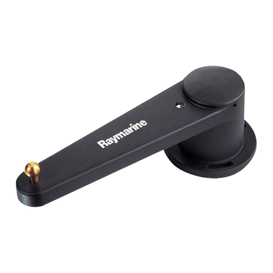
The linear rudder position sensor (part number: M81188) is designed for ‘bullhorn’ style hydraulic outboard steering systems. It is totally weatherproof and designed to be mounted on the bullhorn ram. It transmits the precise position of the boat’s rudder to the autopilot. Linear rudder position sensor - dimensions... - Page 5 7. Place the spacers (supplied) on the bullhorn ram and use adhesive tape to secure them temporarily. 8. Pull out the rudder sensor’s shaft until its alignment mark is level with the end of the barrel. 9. Position the rudder sensor against the spacers so the threaded rod end of its shaft passes through the U-bracket.
-
Page 6: Connecting To The Course Computer
Note: To allow for the bullhorn’s movement, leave a loop of cable at the end of the linear rudder position sensor. If the standard cable is not long enough, your Raymarine dealer can supply a 10 m (30 ft) extension cable (part number: D173). - Page 7 Linear Rudder Position Sensor...
-
Page 8: Emc Installation & Service Guidelines
Raymarine EMC Guidelines EMC Installation & Service Guidelines IMPORTANT NOTE All Raymarine equipment and accessories are designed to the best industry standards for use in the leisure marine environment. When powered up, all electrical equipment produces electromagnetic fields. These can cause adjacent pieces of electrical equipment to interact with one another, with a consequent adverse effect on operation. -
Page 9: Suppression Ferrites
Always use the ferrites supplied by Raymarine. Connections to Other Equipment If your Raymarine equipment is to be connected to other equipment using a cable not supplied by Raymarine, a suppression ferrite MUST always be fitted to the cable close to the Raymarine unit. -
Page 10: Limited Warranty Certificate
During this period, except for certain products, travel costs (auto mileage and tolls) up to 100 round trip highway miles (160 kilometres) and travel time of 2 hours, will be assumed by Raymarine only on products where proof of installation or commission by authorized service agents, can be shown. -
Page 11: Factory Service Centers
Factory Service Centers United States of America Raymarine Inc 22 Cotton Road, Unit D Nashua, NH 03063-4219, USA Telephone: +1 603 881 5200 Fax: +1 603 864 4756 www.raymarine.com Sales & Order Services Telephone: +1 800 539 5539 Ext. 2333 or +1 603 881 5200 Ext.
Need help?
Do you have a question about the Rudder and is the answer not in the manual?
Questions and answers