
Subscribe to Our Youtube Channel
Related Manuals for Raymarine RayPilot 650


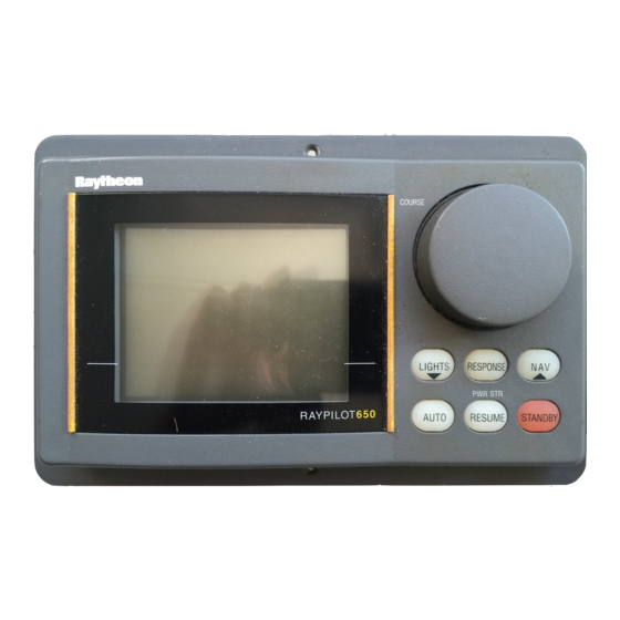
Summary of Contents for Raymarine RayPilot 650
- Page 1 Distributed by Any reference to Raytheon or RTN in this manual should be interpreted as Raymarine. The names Raytheon and RTN are owned by the Raytheon Company.
- Page 2 RayPilot 650 Control Unit Owner’s Handbook Document number: 81013-4 Date: July 2001...
- Page 3 RayPilot 650 Control Unit - Owner’s Handbook Autohelm, HSB (High Speed Bus), SailPilot, SeaTalk and SportPilot are registered trademarks of Raymarine Ltd. Raymarine, AST (Advanced Steering Technology), AutoAdapt, AutoLearn, AutoRelease, AutoSeastate, AutoTack, AutoTrim, FastTrim, GyroPlus, RayGyro, RayPilot and WindTrim are trademarks of Raymarine Ltd.
-
Page 4: Table Of Contents
Preface Contents Chapter 1: Introduction ...1 Chapter 2: Using the RayPilot 650 ...7 1.1 Overview ... 1 1.2 About this handbook ... 3 Important Information ... 3 2.1 Overview ... 7 2.2 Auto mode ... 8 Features ... 8 2.3 Navigation (Track) mode ... 9 Features ... - Page 5 Chapter 3: Maintenance & Fault Finding ...27 Chapter 4: Installing the RayPilot 650 ...31 Chapter 5: Commissioning the Autopilot ...39 Chapter 6: Adjusting Autopilot Settings ...55 RayPilot 650 Control Unit - Owner’s Handbook 3.1 Maintenance ... 27 3.2 Servicing ... 28 3.3 Product support ...
-
Page 6: Chapter 1: Introduction
1.1 Overview Congratulations on the purchase of your RayPilot 650 autopilot control unit from Raymarine. We have developed the RayPilot 650 to integrate simplified controls with a sophisticated processor to bring you superb steering, no matter what the conditions. The totally waterproof control unit has features such as: •... -
Page 7: Emc Conformance
If the RayPilot 650 is used as part of a course computer system, you can connect NMEA 0183 transmitting equipment to the ports on the course computer. With an optional SeaTalk/NMEA interface (part number: E85001), you can also connect NMEA 0183 equipment to the SeaTalk ports on the RayPilot 650. -
Page 8: About This Handbook
Chapter 1: Introduction 1.2 About this handbook Part 1: Using the RayPilot 650 This part of the handbook explains how to use your RayPilot 650: Chapter 2: Using the RayPilot 650 How to use the RayPilot 650 Chapter 3: Maintenance & Fault Finding Provides maintenance and fault finding information. - Page 9 Your Raymarine autopilot will add a new dimension to your boating enjoyment. However, it is the skipper’s responsibility to ensure the safety of the boat at all times by following these basic rules: •...
- Page 10 Part 1: Using the RayPilot 650...
-
Page 12: Chapter 2: Using The Raypilot 650
Chapter 2: Using the RayPilot 650 Chapter 2: Using the RayPilot 650 2.1 Overview This section of the manual provides instructions for the operation of your RayPilot 650. The section starts by explaining the information available on the control head display. A key by key guide follows, which doubles as a useful reference lookup once you are familiar with the pilot’s... -
Page 13: Auto Mode
AUTO - it is that simple. Course changes can be made by adjusting the knob so that the required new heading is displayed. The RayPilot 650 will then automatically turn the boat onto the new course. The maximum rate of turn is governed by a preset turn limit, so even large course changes at speed are accomplished safely. -
Page 14: Navigation (Track) Mode
We have developed this combination with safety utmost in mind. When you reach your target waypoint, the RayPilot 650 will sound an alarm and display the bearing to the next waypoint along with the direction in which the boat will turn. You then check to see the turn can be made safely. -
Page 15: Power Steer
If you require helm to port simply rotate the knob to port, helm to starboard turn the knob to starboard. The RayPilot 650 provides a continuous display of rudder position, allowing you to position the helm accurately for steering in any situation. -
Page 16: Display And Keypad
Rudder/XTE Autopilot Mode Keypad The RayPilot 650 keypad is designed for quick and simple operation. Each time a key is pressed a single audio beep confirms entry. The 6 keys have adjustable backlighting for night-time operation. Cross Track Error or Rudder Angle... -
Page 17: Key Functions
Press and hold for 4 seconds to select compass heading alignment. • Press and hold for 6 seconds to view software version. • Press and hold for 16 seconds to access Calibration mode. RayPilot 650 Control Unit - Owner’s Handbook... - Page 18 Chapter 2: Using the RayPilot 650 AUTO and STBY Press AUTO and STBY together from any other mode to enter • Wind Vane mode • Momentary press (while in Auto or Wind Vane Mode) flashes the display between bearing to waypoint and direction the vessel will turn.
- Page 19 Note: You can make permanent adjustments to response and rudder gain in Calibration mode. LIGHTS and RESP Momentary press of LIGHTS and RESP together will switch on • the Watch Alarm timer (not available from Standby or Power Steer modes). RayPilot 650 Control Unit - Owner’s Handbook...
- Page 20 Chapter 2: Using the RayPilot 650 RESP and NAV Momentary press of RESP and NAV together will switch the • display between cross track error and rudder angle (displayed value and scale). RESUME (PWR STR) • From Standby mode: •...
- Page 21 3 = Maximum level • • Press for 2 seconds to select display contrast adjustment, of which there are 2 levels. L (NAV) and M (LIGHTS) keys • Push to increase or decrease any adjustable function. RayPilot 650 Control Unit - Owner’s Handbook...
-
Page 22: Course Change Knob
Adjusts values in Calibration mode Watch alarm The RayPilot 650 has a built in Watch Alarm. This is a timer that flashes after 3 minutes and sounds an alarm on each control unit a minute later. To silence the alarm and reset the watch alarm to 4 minutes, press a key or rotate the course change knob. -
Page 23: Response Control
Note: You will lose these temporary changes to response level whenever the system is powered off. You can make permanent adjustments in Calibration mode. RayPilot 650 Control Unit - Owner’s Handbook ( NAV ) or ( LIGHTS ) key or course change knob to... -
Page 24: Adjusting Response - Types 150/400 And 100/300
Chapter 2: Using the RayPilot 650 Adjusting response – Types 150/400 and 100/300 To adjust the performance of Type 150/400 (without GyroPlus) and Type 100/300 autopilot systems you can change the response level. Response level – Types 150/400 and 100/300 The response level controls the relationship between the autopilot’s... -
Page 25: Alarms And Warnings
The Waypoint Change alarm sounds in Navigation (Track) mode when the target waypoint from the navigation aid changes. The display alternates between the direction the boat will turn and the bearing to the next waypoint in the route. RayPilot 650 Control Unit - Owner’s Handbook... -
Page 26: Low Battery Alarm
Chapter 2: Using the RayPilot 650 Low Battery alarm The Low battery alarm sounds in all modes when the battery voltage falls below 11.2 V (on 12 V installations) or 21 V (on 24 V installations). No Drive alarm The No Drive alarm sounds in all modes if the drive unit is electrically disconnected. -
Page 27: Data Invalid Alarm
Large XTE (Cross Track Error) alarm The Large XTE alarm sounds in Navigation (Track) mode when cross track error is greater than 0.3 nm. RayPilot 650 Control Unit - Owner’s Handbook... -
Page 28: Joystick Operation
To engage joystick control, press the control button (located in the center of the lever) once. The RayPilot 650 will then display a POWER STEER legend along with the current heading. The joystick can operate in either Proportional or Bang-Bang mode. - Page 29 RayPilot 650 Control Unit - Owner’s Handbook Proportional mode - applying port rudder Small Helm Angle Large Helm Angle D997-1 Proportional mode - applying starboard rudder Small Helm Angle Large Helm Angle D998-1...
-
Page 30: Bang-Bang Mode
Chapter 2: Using the RayPilot 650 Bang-Bang mode Bang-Bang (drive left – drive right) mode applies continuous rudder drive in the direction of joystick movement. To improve control, the speed of rudder movement changes with the angle of the lever: for maximum speed push the lever hardover. -
Page 31: Raypilot 650 Control Unit - Owner's Handbook
RayPilot 650 Control Unit - Owner’s Handbook... -
Page 32: Chapter 3: Maintenance & Fault Finding
3.1 Maintenance CAUTION: The RayPilot control unit does NOT contain any user serviceable parts. It should be repaired only by authorized Raymarine service representatives. Maintaining satisfactory operation of your RayPilot and system components will depend on how well you care for the equipment. -
Page 33: Servicing
3.2 Servicing WARNING: The RayPilot 650 control unit has an electro-fluorescent panel to provide display backlighting. The circuitry used to drive this panel generates approximately 300 V. You must NOT operate the unit is with its cover removed. -
Page 34: Chapter 4: Installing The Raypilot 650
Part 2: Installing the RayPilot 650... -
Page 36: Planning The Installation
Chapter 4: Installing the RayPilot 650 Chapter 4: Installing the RayPilot 650 4.1 Planning the installation Before you start installing your RayPilot 650, read through the following information to help you determine where to locate the RayPilot and route its cables. -
Page 37: Connections To Other Equipment
Always use these ferrites supplied by Raymarine. Connections to other equipment If your Raymarine equipment is to be connected to other equipment using a cable not supplied by Raymarine, a suppression ferrite MUST always be attached to the cable near to the Raymarine unit. -
Page 38: Mounting The Control Unit
Chapter 4: Installing the RayPilot 650 4.2 Mounting the control unit The RayPilot control unit is fully weather protected and is designed for above or below deck installation. Connection to the course computer is made via the SeaTalk bus. RayPilot control units can be mounted on a chart tabletop, suspended overhead or attached to a bulkhead using the bracket supplied. -
Page 39: Bracket Mounting
2. Attach the bracket to the selected location with the screws, washers, seating washers, lock washers and nut. 3. Slide the RayPilot control unit into the bracket and secure in position by tightening the knobs. RayPilot 650 Control Unit - Owner’s Handbook Washer Screw Seating... -
Page 40: Console Mounting
Chapter 4: Installing the RayPilot 650 Console mounting Rubber spacer 1. Select a clear location at least 228 mm x 127 mm (9 in x 5 in) by 127 mm (5 in) deep. 2. Attach the supplied template to the console and drill a pilot hole inside the rectangular hole. -
Page 41: Cabling
2. Run the SeaTalk cable back to the course computer, bearing in mind the EMC and cabling guidelines at the start of this chapter. Note: If the control unit is not the main autopilot control unit, run the SeaTalk cable to the main control unit and connect to the free SeaTalk socket on the rear of the unit. -
Page 42: Joystick Installation (Optional)
Chapter 4: Installing the RayPilot 650 4.3 Joystick installation (optional) Note: The joystick is an option for Type 100/300 course computers. Mounting The mounting surface must be smooth and flat to insure that there is adequate waterproofing. 1. Use the template provided to mark the centers for the two fixing holes and outline of the body aperture. - Page 43 RayPilot 650 Control Unit - Owner’s Handbook...
-
Page 44: Chapter 5: Commissioning The Autopilot
WARNING: All new autopilot system installations MUST be calibrated. If you have connected the RayPilot 650 to a newly installed course computer autopilot system, you must commission the system This involves a series of dockside checks and then the seatrial... -
Page 45: Step 2 - Check The Seatalk And Nmea Connections
If the rudder bar display moves to port: • turn off the power reverse the red and green wires connected to the RUDDER • inputs on the course computer • switch on the power and re-check RayPilot 650 Control Unit - Owner’s Handbook... - Page 46 Chapter 5: Commissioning the Autopilot Check the autopilot steering sense 1. Manually center the wheel, then press the AUTO key so the autopilot is in Auto mode. Check that the display shows AUTO . Be ready to press standby if the rudder moves hardover. 2.
- Page 47 CAUTION: If the installation is a non Raymarine Constant Running Pump, firstly check that the system includes a pressure relief valve. Failure to do this could cause damage to the steering system.
-
Page 48: Step 4 - Adjust Basic Autopilot Settings
Chapter 5: Commissioning the Autopilot Step 4 - Adjust basic autopilot settings The next step in the dockside set-up is to enter Calibration mode so you can adjust some basic autopilot settings. Enter Calibration mode 1. Start with the autopilot in Standby mode. 2. - Page 49 3. Use the set the rudder limit to 5° less than the lowest angle you have noted. RayPilot 650 Control Unit - Owner’s Handbook ( NAV ) or ( LIGHTS ) key or course change knob to Linear drive, rotary drive or I/O (stern) drive...
-
Page 50: Save The New Settings
Chapter 5: Commissioning the Autopilot Adjust the rudder damping Note: You only need to adjust the rudder damping value if the autopilot ‘hunts’ when trying to position the rudder. Increasing the rudder damping value reduces hunting. To adjust the rudder damping: 1. -
Page 51: Initial Seatrial
NMEA compass for information about calibration. Depending on your boat type, deviating magnetic fields can cause significant compass errors. The correction procedure reduces these errors to a few degrees, so you MUST perform this procedure as the RayPilot 650 Control Unit - Owner’s Handbook... -
Page 52: Automatic Compass Deviation Correction
Chapter 5: Commissioning the Autopilot first item in your initial seatrial. The autopilot will then automatically correct the fluxgate compass. CAUTION: If you fail to complete the deviation correction, your autopilot’s performance will be impaired on some compass headings. The deviation correction procedure (swinging the compass) involves turning your boat in slow circles so the autopilot can determine the deviation and calculate any correction required. -
Page 53: Adjusting The Heading Alignment
2. Use the course change knob to adjust the displayed heading until it matches the boat’s steering compass or a known transit bearing. 3. Press STBY for 2 second to save changes and return to Standby. RayPilot 650 Control Unit - Owner’s Handbook... -
Page 54: Adjusting Autopilot Settings
Chapter 5: Commissioning the Autopilot Adjusting autopilot settings The next stage of the seatrial is to set key autopilot parameters that affect the autopilot’s steering characteristics. You need to manually adjust the rudder gain, counter rudder and AutoTrim settings, based on your observations of the boat’s performance under autopilot control. - Page 55 3. Press and hold STBY for 2 seconds to save the changes. 4. Press AUTO to check the autopilot performance in Auto mode. RayPilot 650 Control Unit - Owner’s Handbook heading Rudder setting too low...
- Page 56 Chapter 5: Commissioning the Autopilot Adjusting rudder gain - high speed planing craft WARNING: It is particularly important to set rudder gain correctly on high speed craft. Incorrect adjustment will lead to poor steering performance and this can be dangerous at high speed. Adjust rudder gain as follows: •...
-
Page 57: Further Adjustments
(caused, for example, by changes in the wind load on the sails or superstructure, or an imbalance of engines). RayPilot 650 Control Unit - Owner’s Handbook ( NAV ) and ( LIGHTS ) keys or course change knob... - Page 58 Chapter 5: Commissioning the Autopilot Gain experience with your autopilot before attempting to adjust the AutoTrim setting. On sail boats you can only evaluate the effect of AutoTrim while under sail. Increasing the AutoTrim level reduces the time the autopilot takes to get back onto the correct course, but makes the boat less stable: •...
- Page 59 RayPilot 650 Control Unit - Owner’s Handbook...
-
Page 60: Chapter 6: Adjusting Autopilot Settings
Chapter 6: Adjusting Autopilot Settings Chapter 6: Adjusting Autopilot Settings This chapter explains all of the calibration settings you can adjust on the autopilot system. You will have adjusted many of these settings when commissioning the system (see Chapter 5), and they should not require further adjustment. -
Page 61: Type 150/150G And 400/400G Course Computers
Note: To exit Calibration mode without saving changes, press STBY momentarily. Calibration screens When you use the RayPilot 650 with a Type 150/150G or Type 400/400G course computer, the calibration screens appear in the following order: Calibration lock (CAL LoC) This screen controls whether it is possible to access the compass deviation and alignment screens. - Page 62 Chapter 6: Adjusting Autopilot Settings Vessel type (vES tYP) Vessel type should be set when commissioning the autopilot. Options Note: When you select the vessel type, the autopilot will set appropriate defaults for several other calibration settings. Refer to the table on page 64 for default values. Drive type (drv oPt) The drive type setting controls how the autopilot drives the steering system.
- Page 63 Adjust the rudder damping value if the autopilot ‘hunts’ when trying to position the rudder. Increasing the rudder damping value reduces hunting. Screen text rUd dPG RayPilot 650 Control Unit - Owner’s Handbook Range 10° to 40° in 1° steps Range 1 to 9...
- Page 64 Chapter 6: Adjusting Autopilot Settings AutoTrim (tr LEv) The AutoTrim setting determines the rate at which the autopilot applies ‘standing helm’ to correct for trim changes caused by varying wind loads on the sails or superstructure. The default AutoTrim is set when commissioning the autopilot. If you need to change the setting, increase the AutoTrim one level at a time and use the lowest acceptable value: •...
- Page 65 This limits your boat’s rate of turn under autopilot control. Screen text trn rtE RayPilot 650 Control Unit - Owner’s Handbook • level 1 gives the least pilot activity to conserve power, but may compromise short-term course-keeping accuracy • levels 4 to 6 should give good course keeping with crisp, well controlled turns under normal operating conditions •...
- Page 66 Chapter 6: Adjusting Autopilot Settings Off course warning angle (oFF CrS) This screen determines the angle used by the Off Course warning. The Off Course warning operates if the pilot strays off course by more than the specified angle for more than 20 seconds. Screen text oFF CrS AutoRelease (I/O drives only) (AUt rLS)
- Page 67 Note: If you set AutoAdapt to 1 or 2 , you then need to enter your current latitude in the next screen (Latitude), so that the autopilot can provide accurate course keeping by automatically adjusting the RayPilot 650 Control Unit - Owner’s Handbook Options Range = 1 to 9...
- Page 68 Chapter 6: Adjusting Autopilot Settings rudder gain depending on the heading. If you have a GPS connected, the autopilot will take latitude information from the GPS. with compensation Latitude (LAt) The RayPilot only displays this screen if you have set AutoAdapt to 1 or 2 .
-
Page 69: Calibration Defaults: Types 150/150G & 400/400G
Drive type Rudder alignment 0 Rudder limit Rudder gain Counter rudder Rudder damping AutoTrim Response: with G non-G Turn rate limit Off course angle AutoRelease Wind Trim Cruise speed AutoAdapt Latitude Variation RayPilot 650 Control Unit - Owner’s Handbook Vessel type... -
Page 70: Calibration Options: Types 150/150G & 400/400G
Chapter 6: Adjusting Autopilot Settings Calibration options: Types 150/150G & 400/400G Calibration setting Calibration lock Vessel type 1 = DISPLACE, 2 = SEMI DISPLACE, 3 = PLANING, 4 = STERN DRV, Drive type Rudder alignment Rudder limit Rudder gain Counter rudder Rudder damping AutoTrim Response... -
Page 71: Type 100/300 Course Computers
Note: To exit Calibration mode without saving changes, press STBY momentarily. Calibration screens When you use the RayPilot 650 with a Type 100/300 course computer, the calibration screens appear in the following order: Vessel type (vES tYP) Vessel type should be set when commissioning the autopilot. - Page 72 Chapter 6: Adjusting Autopilot Settings Calibration lock (CAL LoC) This screen controls whether it is possible to access the compass deviation and alignment screens. Options Rudder gain (rUd LEv) This screen determines the default rudder gain setting. Rudder gain is a measure of how much helm the autopilot will apply to correct course errors.
- Page 73 ‘standing helm’ to correct for trim changes caused by varying wind loads on the sails or superstructure.You should set the default AutoTrim after commissioning the autopilot. Setting RayPilot 650 Control Unit - Owner’s Handbook Range 15° to 30° in 1° steps Range 5°...
- Page 74 Chapter 6: Adjusting Autopilot Settings Setting Power steer (JoY) If you have a joystick connected to your Type 100/300 autopilot system, use this screen to select the required joystick mode of operation (see table). Options Drive type (drv oPt) The drive type setting controls how the autopilot drives the steering system.
- Page 75 Options Latitude (LAt) The RayPilot 650 only displays this screen if you have set AutoAdapt to 1 or 2 . Use the RayPilot 650 Control Unit - Owner’s Handbook Range...
- Page 76 Chapter 6: Adjusting Autopilot Settings knob to set the value to your boat’s current latitude, to the nearest degree. Note: If valid latitude data is available via SeaTalk or NMEA, the autopilot will use this data instead of the calibration value. Screen text LATITUDE WindTrim (wind response) (unE tC)
- Page 77 Screen text RayPilot 650 Control Unit - Owner’s Handbook Options AutoSeastate on (Automatic deadband) = default • autopilot to gradually ignores repetitive boat movements and only react to true variations in course • provides the best compromise between power consumption and course keeping accuracy AutoSeastate off (minimum deadband) •...
-
Page 78: Dealer Calibration: Default Settings With Type 100/300
Chapter 6: Adjusting Autopilot Settings Dealer Calibration: default settings with Type 100/300 Calibration setting Vessel type Calibration lock Rudder gain Counter rudder Rudder alignment Rudder limit Turn rate limit Cruise speed Off course angle AutoTrim Power steer Drive type Rudder damping Variation AutoAdapt NORTH... - Page 79 RayPilot 650 Control Unit - Owner’s Handbook...
-
Page 80: Limited Warranty Certificate
During this period, except for certain products, travel costs (auto mileage and tolls) up to 100 round trip highway miles (160 kilometres) and travel time of 2 hours, will be assumed by Raymarine only on products where proof of installation or commission by authorized service agents, can be shown. -
Page 81: Factory Service Centers
Factory Service Centers United States of America Raymarine Inc 22 Cotton Road, Unit D Nashua, NH 03063-4219, USA Telephone: +1 603 881 5200 Fax: +1 603 864 4756 www.raymarine.com Sales & Order Services Telephone: +1 800 539 5539 Ext. 2333 or +1 603 881 5200 Ext.
Need help?
Do you have a question about the RayPilot 650 and is the answer not in the manual?
Questions and answers