
Subscribe to Our Youtube Channel
Related Manuals for Raymarine Pathfinder GyroPlus 2


Summary of Contents for Raymarine Pathfinder GyroPlus 2
- Page 1 Pathfinder Smart Heading System Owner’s Handbook Document Number: 81198-1 Date: February 2002...
- Page 2 In addition, our policy of continuous product improvement may change specifications without notice. As a result, Raymarine cannot accept liability for any differences between the product and the handbook. Copyright Information Autohelm, HSB (High Speed Bus), SailPilot, SeaTalk and SportPilot are registered trademarks of Raymarine Ltd.
-
Page 3: Table Of Contents
Preface Contents About this Handbook .....................v Important Information ..............v Warranty ..................vi Safety notices ................vi EMC conformance ..............vi Chapter 1: Introduction ..................1 1.1 System overview ................1 1.2 System components ..............2 Fluxgate compass ................. 2 GyroPlus 2 unit ................2 1.3 Using the Smart Heading System .......... - Page 4 Connecting to T150 or T400 course computers ......27 Installation instructions for T150/T400 ........29 Calibration .................. 29 Integrating with other Raymarine autopilots ......30 Connecting to ST4000+ or ST5000+ autopilot ......30 Connecting to T100 or T300 course computer ......31...
-
Page 5: About This Handbook
At the end of this handbook we have included product specifications and warranty certificate. Note: This handbook contains important information about installing, using and maintaining your new Raymarine product. To get the best from the product, please read this handbook thoroughly. Important Information Before using this product, please read the following information about: •... -
Page 6: Warranty
Pathfinder Smart Heading System - Owner’s Handbook Warranty To register your new Raymarine product, please take a few minutes to fill out the warranty card. It is important that you complete the owner information and return the card to us to receive full warranty benefits. -
Page 7: Chapter 1: Introduction
MARPA and radar/chart overlay features on Pathfinder Plus radars and chartplotters. It is designed to operate as part of an integrated Raymarine system, and can be calibrated using a Raymarine Pathfinder Plus display or a Raymarine autopilot control unit. -
Page 8: System Components
Note: The GyroPlus 2 unit is primarily designed to be used as part of the Smart Heading System. However, it can also be used as a ‘stand alone’ sensor to provide rate of turn information for Raymarine course computers. Refer to the Appendix for more information. -
Page 9: Chapter 2: Installation
16 WARNING: Calibration requirement You MUST calibrate the Smart Heading System after installation using a suitable Raymarine autopilot or Pathfinder Plus display (see Chapter 3: Calibration). Note: Refer to the Appendix first if you are connecting the GyroPlus 2... -
Page 10: Planning The Installation
Adding the GyroPlus 2 unit to an autopilot Refer to the Appendix if you need to add only the GyroPlus 2 unit to a Raymarine autopilot (which has an existing fluxgate compass). Connecting to a single Pathfinder Plus If you connect the Smart Heading System to a single Pathfinder Plus (with no other SeaTalk instruments), you will need to provide power to the GyroPlus 2 unit direct from the distribution panel (see page 11). - Page 11 Chapter 2: Installation Connecting to a single Pathfinder Plus Radar Scanner Pathfinder Plus Radar Fluxgate Compass GyroPlus 2 Unit NMEA out SeaTalk (for calibration not power) Power Power 12/24V 12/24V D5921-2 Connecting to Pathfinder Plus and SeaTalk instruments If you connect the Smart Heading System to both a Pathfinder Plus unit and an existing SeaTalk system, you can provide power either through SeaTalk (as shown below) or direct from the distribution panel.
-
Page 12: Tools Required
Pathfinder Smart Heading System - Owner’s Handbook Tools required • drill and 3 mm ( in) drill bit • cross-head/pozi-drive screwdriver • small flat-bladed screwdriver (for GyroPlus 2 unit terminals) • wire-strippers • hand bearing compass (to help identify suitable fluxgate location) Parts required Smart Heading System - parts supplied Fluxgate compass... -
Page 13: Emc Installation Guidelines
Chapter 2: Installation EMC installation guidelines All Raymarine equipment and accessories are designed to the best industry standards for use in the recreational marine environment. Their design and manufacture conforms to the appropriate Electromagnetic Compatibility (EMC) standards, but correct installation is required to ensure that performance is not compromised. -
Page 14: Installing The Gyroplus 2 Unit
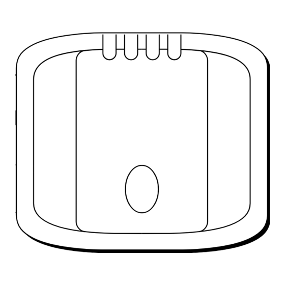
Pathfinder Smart Heading System - Owner’s Handbook 2.2 Installing the GyroPlus 2 unit GyroPlus 2 unit - dimensions 39 mm 150 mm (5.9 in) (1.5 in) D5915-1 GyroPlus 2 unit - inputs/outputs GyroPlus 2 unit - inputs/outputs Fluxgate compass in NMEA 0183 in Not used NMEA 0183 out... -
Page 15: Site Requirements
Chapter 2: Installation Site requirements CAUTION: The GyroPlus 2 unit is not waterproof, so it MUST be installed in a dry location away from water splash or spray from bilges, hatches, etc. Mount the GyroPlus 2 unit below deck, in a dry location that is: •... -
Page 16: Mounting The Gyroplus 2 Unit
Pathfinder Smart Heading System - Owner’s Handbook Mounting the GyroPlus 2 unit Fit the GyroPlus 2 unit to the vertical surface as follows: 1. Remove the outer cover (as shown below). D5918-2 2. Temporarily hold the GyroPlus 2 unit in the required position so you can mark the centers of the two fixing holes. - Page 17 Chapter 2: Installation GyroPlus 2 unit - power supply As described at the start of this Chapter, you can provide power to the GyroPlus 2 unit either: • via SeaTalk (12 V) • direct from your boat’s distribution panel (12 V or 24 V): using suitable cable protected with a 3 A in-line fuse or equivalent circuit breaker Note: If you connect power to both the SeaTalk terminals and the...
-
Page 18: Installing The Fluxgate Compass
Pathfinder Smart Heading System - Owner’s Handbook 2.3 Installing the fluxgate compass Fluxgate compass - description and dimensions The fluxgate compass contains a self-levelling mechanism. This enables the compass to provide accurate readings with pitch and roll movements up to +/- 35°. 76 mm (3 in) 76 mm (3 in) D5381-1... - Page 19 Chapter 2: Installation Note: Because the compass is electronically aligned after installation (see Chapter 3: Calibration), you can mount it so it faces in any direction. D5382-1 Figure 2-2: Compass - recommended location for non-steel hulls Finding the most suitable location To identify the best compass location on your boat, start at the pitch and roll center then move the compass up and/or aft until you find a location with minimal magnetic disturbance.
-
Page 20: Mount The Fluxgate Compass
Pathfinder Smart Heading System - Owner’s Handbook The following diagram shows recommended mounting positions for steel-hulled boats. Note: The higher above the waterline you mount the compass, the more the boat’s pitch and roll will affect compass performance. 1.8 m (6 ft) 1.2 m (4 ft) 1.2 m (4 ft) D5383-2... -
Page 21: Connect The Fluxgate Compass To The Gyroplus 2 Unit
Chapter 2: Installation Figure 2-4: Fluxgate compass - orientation Note: Stick the supplied warning label near to the fluxgate compass, where it is clearly visible. Connect the fluxgate compass to the GyroPlus 2 unit 1. The fluxgate compass is supplied with 8 m (26 ft) of cable. Route the cable to the GyroPlus 2 unit, taking into account the EMC installation guidelines (see page 7). -
Page 22: Connecting To Pathfinder Plus
Pathfinder Smart Heading System - Owner’s Handbook 2.4 Connecting to Pathfinder Plus You need to connect the GyroPlus 2 unit to the Pathfinder Plus using both NMEA and SeaTalk: • the SeaTalk connection allows the Pathfinder Plus unit to calibrate the compass •... - Page 23 Chapter 2: Installation Connecting to more than one Pathfinder Plus unit You can use the NMEA out terminals on the GyroPlus 2 unit to supply fast heading information to up to ten Pathfinder Plus units (depending on the length of NMEA cable run). To use MARPA and radar/chart overlay on all units you will need to connect each Pathfinder Plus unit directly to the NMEA out terminals on the GyroPlus 2 unit, so they receive fast heading data.
- Page 24 Pathfinder Smart Heading System - Owner’s Handbook...
-
Page 25: Chapter 3: Calibration
Note: The Pathfinder Plus display must contain software release 2 (or later) to enable the compass calibration feature. Contact your Raymarine dealer if you need more information or a software upgrade. Note: You can also calibrate the compass system using a Raymarine autopilot (see the Appendix). -
Page 26: Calibrating With A Pathfinder Plus Display
Pathfinder Smart Heading System - Owner’s Handbook 3.2 Calibrating with a Pathfinder Plus display Step 1: Enter Compass Setup mode 1. Press the MENU button. 2. Press the SYSTEM SET UP soft key. You will then see the SYSTEM SET UP MENU. -
Page 27: Step 2: Linearise The Compass
Chapter 3: Calibration Step 2: Linearise the compass LINEARISE ALIGN LINEARISE LINEARISE COMPASS HEADING COMPASS COMPASS D5953-1 1. Press the LINEARISE COMPASS soft key to start the linearising process. Note: If you see a WARNING - COMPASS NOT CONNECTED message, check your Smart Heading System connections. -
Page 28: Step 3: Align The Heading
Pathfinder Smart Heading System - Owner’s Handbook 4. When compass linearisation is complete, the Pathfinder Plus unit will beep and briefly display the following pop-up message. LINEARISATION COMPLETE. ALIGN HEADING TO KNOWN REFERENCE D5956-1 5. You will then see the ALIGNING HEADING box, showing the corrected deviation. - Page 29 Chapter 3: Calibration press the ALIGN TO COG soft key: the HEADING value will then be • aligned to the COG (course over ground) heading received from the GPS and you will see the following pop-up message HEADING ALIGNED TO COG. USE ADJUST HEADING KEYS TO FINE TUNE HEADING D5959-1...
- Page 30 Pathfinder Smart Heading System - Owner’s Handbook...
-
Page 31: Chapter 4: Fault-Finding & Maintenance
Chapter 4: Fault-finding & Maintenance Chapter 4: Fault-finding & Maintenance All Raymarine products are designed to provide many years of trouble-free operation. We also put them through comprehensive testing and quality assurance procedures before shipping. Regular checks CAUTION: The GyroPlus 2 unit and fluxgate compass do NOT contain user- serviceable parts. -
Page 32: Servicing
In order to minimize these effects and enable you to get the best possible performance from your Raymarine equipment, guidelines are given in the installation instructions, to enable you to ensure minimum interaction between different items of equipment, i.e. ensure optimum Electromagnetic Compatibility (EMC). -
Page 33: Appendix: Connecting To Autopilots
Appendix: Connecting to Autopilots Appendix: Connecting to Autopilots The information in this Appendix explains how to connect the GyroPlus 2 unit to the following Raymarine autopilot systems: • connecting to T150 or T400 course computers (Section A.1) • integrating with other Raymarine autopilots (Section A.2) •... - Page 34 Pathfinder Smart Heading System - Owner’s Handbook Connecting to T150/T400 Course Computer ST6001+ SeaTalk Instrument SeaTalk SeaTalk SeaTalk Fluxgate Compass Course Computer GyroPlus 2 unit SeaTalk SeaTalk Gyro Data Power 12/24V D5934-1 Connecting to T150/T400 course computer and Pathfinder Plus Radar Scanner Pathfinder Plus Radar SeaTalk Instrument...
-
Page 35: Installation Instructions For T150/T400
Appendix: Connecting to Autopilots Installation instructions for T150/T400 Fluxgate compass Leave the compass connected to course computer FLUXGATE inputs. Installing the GyroPlus 2 unit Follow the installation instructions for the GyroPlus 2 unit in Chapter 2. CAUTION: If you are using the Smart Heading System as the primary heading reference for an autopilot, you must ensure that it receives power (via SeaTalk or direct from the distribution panel) when the autopilot is switched on. -
Page 36: Integrating With Other Raymarine Autopilots
Pathfinder Smart Heading System - Owner’s Handbook A.2 Integrating with other Raymarine autopilots If you already have a Raymarine fluxgate compass mounted in a suitable location as part of your autopilot system (not T150/T400), you need to: • install GyroPlus 2 unit and connect the existing SeaTalk system to the... -
Page 37: Connecting To T100 Or T300 Course Computer
Appendix: Connecting to Autopilots Connecting to T100 or T300 course computer Radar Scanner Connecting to T100 or T300 course computer (and Pathfinder Plus) Pathfinder Plus Radar SeaTalk Instrument ST6000+ or ST6001+ SeaTalk SeaTalk SeaTalk Fluxgate Compass T100 or T300 Course Computer GyroPlus 2 Unit NMEA out SeaTalk... -
Page 38: Specifications
Pathfinder Smart Heading System - Owner’s Handbook Specifications GyroPlus 2 unit Nominal supply voltage: 12 V or 24 V DC Operating voltage range: 10 V to 32 V DC Power consumption (max): 130 mA Operating conditions: temperature range -10°C to 55°C (14°F to 131°F) relative humidity limit water protection drip resistant when mounted vertically... - Page 39 During this period, except for certain products, travel costs (auto mileage and tolls) up to 100 round trip highway miles (160 kilometres) and travel time of 2 hours, will be assumed by Raymarine only on products where proof of installation or commission by authorized service agents, can be shown.
- Page 40 Factory Service Centers United States of America UK, Europe, Middle East, Far East Raymarine Inc Raymarine Ltd 22 Cotton Road, Unit D Anchorage Park, Portsmouth Nashua, NH 03063-4219, USA PO3 5TD, England Telephone: +1 603 881 5200 Telephone: +44 (0)23 9269 3611...
Need help?
Do you have a question about the Pathfinder GyroPlus 2 and is the answer not in the manual?
Questions and answers