
Related Manuals for Alemite 3690-D Series


Summary of Contents for Alemite 3690-D Series
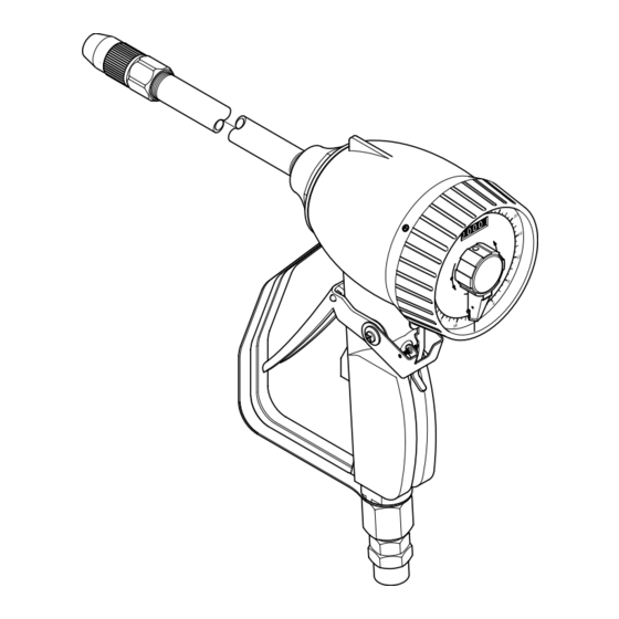
- Page 1 Service guide Preset metered control valve -C, -D*, -C, -C, -C Date of issue June 2022 Form number 670868 Version Indicates change.
-
Page 2: Table Of Contents
Contents Safety ......Explanation of signal words for safety ......... -
Page 3: Safety
Safety Explanation of signal words for safety Read and carefully observe installation instructions before installing/operating/ troubleshooting the assembly. Assembly NOTE must be installed, maintained and repaired Emphasizes useful hints and exclusively by persons familiar with recommendations as well as instructions. information for efficient and trouble- Install assembly only after safety free operation. -
Page 4: Description
Description Table 1 Preset metered control valve models 3690-C, 3690-D*, 3691-C, 3693-C, 3696-C Register units Preset metered valves are designed to Valve model Inlet Current (w/range) Totalizer Accuracy Maximum pressure dispense preset quantities of fluid lubricants. Each model is equipped with an inlet swivel, -C in NPTF Quart (... -
Page 5: Overhaul
Overhaul Disassembly Metering mechanism assembly Prior to performing any maintenance on equipment, the following safety precautions 17 Unscrew cap (3) from housing (8). NOTE must be observed. Personal injury may 18 Remove o-ring (4) from cap (3). Refer to Fig. IPB 1, page 10 for occur. -
Page 6: Clean And Inspect
Clean and inspect Metered control valve NOTE Make sure worm gear (13) setscrew 1 Clean all metal parts in cleaning solvent. Metering mechanism assembly points toward flat on spindle and gear Solvent should be environmentally safe. assembly (7). Verify gear meshes 2 Inspect all parts for wear and/or 1 Install and seat washer (9) into head of properly with register gear. -
Page 7: Pointer, Cam And Dial Assembly
Pointer, cam and dial 35 Install lever assembly (40) onto cam (37). assembly 23 Install dial (27) onto cam (17). 24 Install rollers (19) into cam. NOTE Reposition cam (37) as required to ensure lever assembly properly meshes. NOTE Make sure spring (18) is against right-angled end of notch in cam (17). -
Page 8: Troubleshooting Chart
Troubleshooting chart Control valve indications Possible problems Solutions Reduced or zero flow. . Filter screen (31) clogged. . Removed filter screen (31) and clean or replace. . Clogged system. . Clean or replace system filter. No product flow. . Nozzle (1) not open. . -
Page 9: Common Parts List
Common parts list Item Decsription Part number Quantity Non-drip nozzle, high-volume manual O-ring (Buna-N) - Gear, planetary (included w/item )) Housing Washer (Buna-N) - ) O-ring (Buna-N) -... -
Page 10: Illustrated Parts Breakdown
Fig. IPB 1 Preset metered control valve, exploded view 21 22 ) Apply thread sealant ) Part of packing gland kit - ) Apply threadlocker ) Setscrew access hole ... - Page 11 This page left intentionally blank. ...
- Page 12 ® Alemite, LLC is a registered trademark. The contents of this publication are the copyright of the publisher and may not be reproduced (even extracts) unless prior written permission is granted. Every care has been taken to ensure the accuracy of the information contained in this publication but no liability can be accepted for any loss or damage whether direct, indirect or consequential arising out of the use of the information contained herein.
Need help?
Do you have a question about the 3690-D Series and is the answer not in the manual?
Questions and answers