
Related Manuals for Holy Stone SPYDI


Summary of Contents for Holy Stone SPYDI
- Page 1 SPYDI PMN:quadcopter Instructions For Use Gebrauchsanweisung V1.0 +1(855)888-6699 usa@holystone.com (USA) eu@holystone.com (EU) www.holystone.com ca@holystone.com (CA)
- Page 2 CONTENTS Operation Guidance Product Introduction English 01-61 Package Contents Charging Pre-Flight Checklist Diagram of the Drone Pre-Flight Preparations Flight Diagram of the Transmitter Flight Environment Requirements Deutsch 62-119 Product Functions General Information Safety Instructions Flight Functions Specifications Disclaimer & Warning APP Functions Contact Us Safety Guidelines...
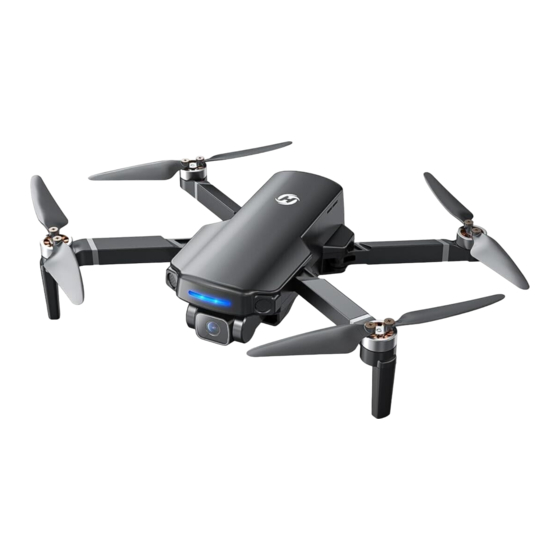
- Page 3 1.2 Diagram of the Drone >> Drone Camera Propeller Motor Camera Cover Drone Status Indicator Optical Flow Module Drone Battery SPYDI Instructions For Use Battery of the Drone Gebrauchsanweisung V1.0 Snap Charging Port (Type-C) Battery Level Indicators Power Switch +1(855)888-6699 usa@holystone.com (USA)
- Page 4 PRODUCT INTRODUCTION PRODUCT INTRODUCTION 1.3 Diagram of the Transmitter >> Transmitter Functions Cellphone Holder Takeoff/Landing: Emergency Stop: Front: Top: Short Press Long Press Left Joystick Speed Switch: GPS Switch on/off: Short Press Long Press Take Photo LCD Screen Check Battery Level : Power Switch: Connection Cable Short Press...
- Page 5 PRODUCT INTRODUCTION PRODUCT INTRODUCTION 1.3 Diagram of the Transmitter >> LCD Screen Transmitter WiFi Signal Transmitter Battery Level GPS Signal Strength Transmitter Signal Strength Photo/Record Indicator Flight Speed Drone Status Drone Battery Level Flight Distance Flight Height Flight Speed Ascend/Descend Speed When the battery level of the transmitter is low, its icon will start to flash.
- Page 6 PRODUCT INTRODUCTION PRODUCT INTRODUCTION 1.3 Diagram of the Transmitter >> Joystick Mode Mode 1: (Right joystick as the throttle joystick) Hold the ( ) button, short press the ( ) button of the transmitter once, then hold Mode 2: (Left joystick as the throttle joystick) the latter until the transmitter quickly beeps 3 times.
- Page 7 OPERATION GUIDANCE OPERATION GUIDANCE Charging of the Drone Battery: 2.1 Charging >> Insert the Type-C plug of the charging cable into the drone battery. Plug the other end of the cable into a USB adapter (5V/2A) or power bank to start charging. When the battery is charging, the battery level indicators will keep flashing.
- Page 8 OPERATION GUIDANCE OPERATION GUIDANCE 2.2 Pre-Flight Preparations >> 2.2 Pre-Flight Preparations >> ① Download & Installation ② Camera Cover ③ Drone Battery ④ Arms Installation: Unfold the front arms Push the battery into the fuselage. Make sure you hear a click when inserting the battery, w h i c h i n d i c a t e s t h a t i t i s installed firmly.
- Page 9 OPERATION GUIDANCE OPERATION GUIDANCE 2.2 Pre-Flight Preparations >> 2.2 Pre-Flight Preparations >> ⑤ Propeller ⑥ TF Card ⑦ Joysticks Installation: Remove: marked Install the marked propellers to the marked Use the screwdriver to turn the screws motor shafts. Use the screwdriver to tighten the anti-clockwise to remove them.
- Page 10 OPERATION GUIDANCE OPERATION GUIDANCE 2.3 Flight Environment Requirements >> 2.4 Pre-Flight Checklist >> Fly in Open Areas Avoid flying over or near obstacles, crowds, high voltage power lines, trees, airports or bodies of water. Make sure the drone battery Make sure the drone arms are Make sure the transmitter, the Avoid flying near areas with magnetic or radio interfer- a n d t h e p r o p e l l e r s a r e...
- Page 11 OPERATION GUIDANCE OPERATION GUIDANCE 2.5 Flight >> Pairing Turning on the transmitter · To avoid unnecessary loss or damage, it is strongly recommended that the pilot flys this drone in Short press the power switch of the transmitter an open, outdoor area. ·...
- Page 12 OPERATION GUIDANCE OPERATION GUIDANCE 2.5 Flight >> App Connection Cellphone connection: Pull the cellphone holder out. Draw out the connection cable Run the "HS FLY" app and open up the live-feed interface. from the transmitter. (A Type-C connection cable is pre-installed. You will also receive a micro-USB and a Lightning type connection cable.) After setting the cellphone into the holder, use the connection cable to connect the trans- mitter with the cellphone.
- Page 13 OPERATION GUIDANCE OPERATION GUIDANCE 2.5 Flight >> 2.5 Flight >> Compass Calibration Unlocking the Motors Takeoff/Landing Unlocking STEP 1 Push both joysticks towards the inner, upper corners simul- taneously to start the compass calibration. Takeoff Short press the ( ) button, the drone slowly takes off.
- Page 14 PRODUCT FUNCTIONS PRODUCT FUNCTIONS 3.1 Flight Functions >> 3.1 Flight Functions >> Camera Adjustment Emergency Stop 90° H<16ft Adjust the camera angle by scrolling the camera adjustment dial ( ) (tilt range: -90°~ 0°) Zoom Hold the ( ) button for 2 seconds to use Emergency Stop. This function only works when the drone's altitude is lower than 16ft.
- Page 15 PRODUCT FUNCTIONS PRODUCT FUNCTIONS 3.1 Flight Functions >> 3.1 Flight Functions >> Speed Switch Photo/Video Short press the ( ) button once to switch speed. The normal mode is the default setting. Photo Video Short press the ( ) button on the transmitter. The ( ) on the LCD screen flashes Low:...
- Page 16 PRODUCT FUNCTIONS PRODUCT FUNCTIONS 3.1 Flight Functions >> GPS Return to Home Failsafe RTH: The GPS Return to Home (RTH) function brings the drone back to the home point. As the name indicated, this function can only be triggered when the drone is in GPS mode. If the transmitter loses the connection with the drone, the Failsafe RTH will be automatically There are 3 types of RTH: Smart RTH, Failsafe RTH and Low Voltage RTH.
- Page 17 PRODUCT FUNCTIONS PRODUCT FUNCTIONS 3.1 Flight Functions >> GPS Return to Home Low Voltage RTH: (The first stageas ) Flight altitude=RA H=RA During the first stage of Low Voltage RTH, the transmitter will keep beeping, and the LCD screen When the flight altitude is equal to RA, the will display "GOING HOME."...
- Page 18 PRODUCT FUNCTIONS PRODUCT FUNCTIONS 3.1 Flight Functions >> GPS Return to Home Low Voltage RTH: (The second stageas ) The transmitter keeps on producing long beeps, the LCD screen displays "GOING HOME," the Flight altitude=66ft battery level bar on the screen keeps flashing. The drone will automatically fly back to the H=66 ft Home Point and land.
- Page 19 PRODUCT FUNCTIONS PRODUCT FUNCTIONS 3.2 APP Functions >> The Interface Homepage( Tap this icon to return to the main menu. System Status( Displays the flight status and various warning messages. Displays the current level of electromagnetic interference. Interference Index of Compass( "0"...
- Page 20 PRODUCT FUNCTIONS PRODUCT FUNCTIONS 3.2 APP Functions >> The Interface The drone ascends and spiral around the subject. A video is made during this (See Spiral Up( page 45). The drone stays at a distance from the operator and follows the GPS position of the GPS Follow( Portrait( The shooting mode will turn from landscape to portrait.
- Page 21 PRODUCT FUNCTIONS PRODUCT FUNCTIONS 3.2 APP Functions >> Beginner Mode The beginner mode is the default operating mode. When in the Beginner mode: The flight distance can not exceed 98 ft. Remove the distance limit: The flight altitude can not exceed 98 ft. After removing the distance limit, the maximum flight distance is extended to 3000 m.
- Page 22 PRODUCT FUNCTIONS PRODUCT FUNCTIONS 3.2 APP Functions >> GPS Follow When the GPS Follow function is enabled, the drone will track your movement by following the Make sure that the drone's flight distance is within 164 ft. Tap the ( ) icon first, GPS signal on your cellphone.
- Page 23 PRODUCT FUNCTIONS PRODUCT FUNCTIONS 3.2 APP Functions >> 3.2 APP Functions >> Point of Interest Catapult Return Path Execution Path ≥7 ft R=16 ft Make sure that the drone is a least 7 ft away from the target. Adjust the camera angle so it points directly to the target.
- Page 24 PRODUCT FUNCTIONS PRODUCT FUNCTIONS 3.2 APP Functions >> 3.2 APP Functions >> One-key Ascension TapFly When using the TapFly, it is recommended to enlarge the map before drawing the flight path. Return Path Execution Path ≥7 ft Tap the ( ) icon, then Tap ( You can tap a dozen of times (but no more than 16) on the phone screen to create a flight path.
- Page 25 PRODUCT FUNCTIONS PRODUCT FUNCTIONS 3.2 APP Functions >> 3.2 APP Functions >> Spiral Up Time-lapse Return Path Execution Path 16 ft Make sure that the drone is about 16 ft away from the target. Adjust the camera angle so it points directly to the target. Tap the ( ) icon, then tap ( ) .
- Page 26 PRODUCT FUNCTIONS PRODUCT FUNCTIONS 3.2 APP Functions >> 3.3 Stabilization Function >> Panorama Optical Flow Positioning 10 ft Optical Flow Module The Optical Flow Positioning System con- The Optical Flow Positioning System is typi- sists of a camera module, which acquires cally used in an indoor environment when Tap the ( ) icon, then tap (...
- Page 27 PRODUCT FUNCTIONS PRODUCT FUNCTIONS 3.3 Stabilization Function >> 3.3 Stabilization Function >> Altitude-Hold Function Optical Flow Positioning The precision of the Optical Flow Positioning System is easily affected by the light intensity and features of the surface textures. Once the image sensor is not working properly, your drone will switch to altitude-hold function automatically.
- Page 28 GENERAL INFORMATION GENERAL INFORMATION 4.1 Specifications >> 4.1 Specifications >> DRONE: TRANSMITTER: Model : HS360S Weight : 249 g/8.78 oz Operating Frequency : 5500-5700 MHz Charging Time : about 2 hours Max Flight Distance : 9842 ft Usage Time : about 2 hours Max Flight Time : 20 minutes (per battery) Operating Temperature Range :14°...
- Page 29 GENERAL INFORMATION SAFETY INSTRUCTIONS 4.2 Contact Us >> 5.1 Disclaimer & Warning >> Please read this Disclaimer & Warning and Safety Guidelines carefully before using our product. This product is not recommended for people under the age of 14. By using this product, you hereby agree Please do not hesitate to contact us if you need further support.
- Page 30 SAFETY INSTRUCTIONS SAFETY INSTRUCTIONS DO NOT use this product to follow any moving vehicles. DO NOT short-circuit the battery by connecting wires or any other metal object to the positive(+) and negative(-) terminals. During the flight, turn off the motors only in case of an emergency. When the battery runs low, return the drone back to your starting point.
- Page 31 SAFETY INSTRUCTIONS SAFETY INSTRUCTIONS 5.3 Maintenance >> 5.5 Compliance Information >> FCC Notice: Clean the drone after each use with a clean, soft cloth. Avoid prolonged exposure to direct sunlight and avoid buildup of heat on the drone or batteries. This device complies with part 15 of the FCC Rules.
- Page 32 SAFETY INSTRUCTIONS SAFETY INSTRUCTIONS RF Exposure: CAN NMB-003 (B): The equipment complies with FCC radiation exposure limits set forth for an uncontrolled environment. RF Exposure This device should be installed and operated with minimum distance 20cm between the radiator & your Radiation Exposure Statement: body.
- Page 33 SAFETY INSTRUCTIONS Indication Below: Product Name: REMOTE CONTROL MODEL/RADIO CONTROLLED Model/Mark: HS360S/HOLYSTONE The Statement of compliance is available at the following address: http://www.holystone.com/Download/CE/HS360S_EU_DOC.pdf This product can be used across EU member states. Manufacturer Information: Manufactured by Xiamen Huoshiquan Import & Export CO.,LTD Address: Unit 1, Room 501, Hongxiang Building, No.258 Hubin Nan Road, Siming District, Xiamen, China +1(855) 888-6699 MADE IN CHINA(CN)
Need help?
Do you have a question about the SPYDI and is the answer not in the manual?
Questions and answers
Drone battery level is charged but real time display (on the transmitter) reads low voltage battery is in the red. How do I fix this.
If the Holy Stone SPYDI drone transmitter shows a low voltage warning even after the battery is charged, try the following steps:
1. Check Battery Installation: Ensure the battery is properly connected to the drone and securely installed.
2. Power Cycle the Battery: Turn the battery off by pressing the power switch for 3 seconds. Wait a few moments, then turn it back on the same way.
3. Check Battery Indicators: Confirm that the battery level indicators light up and show a full or adequate charge.
4. Inspect Charging Cable and Port: Make sure the USB charging cable and Type-C charging port are working and not damaged.
5. Use Original Accessories: Use only the original charging cable and adapter provided with the drone.
If the issue continues, the battery may be faulty and should be replaced.
This answer is automatically generated