Advertisement
Installation
Manual
High Efficiency Air Handlers
2-5 Ton Capacity
R-410A TXV Inside
E4AH5E48A1K30A
E4AH5E60A1K30A
All phases of this installation must comply with National, State and Local Codes.
This document is customer's property and is to remain with this unit. Please return it to customer with
service information upon completion of work.
These instructions are intended as an assist to qualified and licensed personnel for proper installation,
adjustment and operation of ECM air handler units. Read it thoroughly before attempting installation or
service work.
Failure to follow these instructions may result in fire, electrical shock, property damage,
personal injury or death.
The instructions do not cover all varitions in systems or provide for every possible contingency to be met
in connection with the installation.
88-E4AH5001-1B-EN
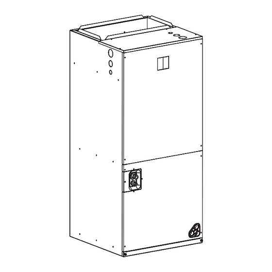
Appearance of unit may vary.
NOTE:
Installation must be performed in accordance
with the requirements of NEC and CEC by
authorized personnel only.
Advertisement
Table of Contents

Related Manuals for Trane E4AH5E24A1J30A


Summary of Contents for Trane E4AH5E24A1J30A
- Page 1 Installation Manual High Efficiency Air Handlers 2-5 Ton Capacity R-410A TXV Inside E4AH5E48A1K30A E4AH5E60A1K30A Appearance of unit may vary. NOTE: Installation must be performed in accordance with the requirements of NEC and CEC by authorized personnel only. All phases of this installation must comply with National, State and Local Codes. This document is customer’s property and is to remain with this unit.
-
Page 2: Table Of Contents
Table of contents 1. Safety ..................3 6. Ductwork ................25 2. Dimensions .................5 7. Air Filter ................26 3. Applications ................7 8. Indoor Unit Function ............27 4. Electrical Wiring .............12 9. Service Manual .............. 29 5. Airflow Performance ............24... -
Page 3: Safety
1. Safety Read the following safety instructions before installing the unit or doing service work. WARNING may cause personal death or serious injury. CAUTION may lead to injury or structural damage under some conditions. WARNING WARNING FIRE HAZARD! PRESSURIZED REFRIGERANT! — IMPROPER REFRIGERANT! WITH HEAT PUMP INSTALLATIONS, SOME ELECTRIC HEATERS ARE POSITION SENSITIVE. - Page 4 WARNING WARNING ROTATING FAN BLADE! USE COPPER CONDUCTORS ONLY! DISCONNECT ALL ELECTRIC POWER INCLUDING UNIT TERMINALS ARE NOT DESIGNED TO ACCEPT REMOTE DISCONNECTS BEFORE SERVICING. OTHER TYPES OF CONDUCTORS. FAILURE TO DISCONNECT POWER BEFORE FAILURE TO DO THE ABOVE COULD RESULT IN SERVICING CAN CAUSE SEVERE PERSONAL INJURY EQUIPMENT DAMAGE.
-
Page 5: Dimensions
2. Dimensions NOTE: 25'' CLEARANCE IS REQUIRED IN THE FRONT OF THE UNIT FOR FILTER AND COIL MAINTENANCE Gas Line Liquid Line Inlet (Front View) Primary drain Inlet (Left Side View) connection 3/4'' Female pipe thread (NPT) Figure 2-1 Unit dimensions... - Page 6 Table 1. Unit Dimensions Dimensions (in.) Model Liquid Line Gas Line Connection Connection E4AH5E24A1J30A 46-1/2 19-1/4 E4AH5E36A1J30A E4AH5E48A1K30A 24-1/2 22-3/4 E4AH5E60A1K30A Select a solid and level site, keep enough space for proper installation and maintenance. Adjust motor speed tap on indoor main control board (MCB) to select correct air flow according to blower performance table.
-
Page 7: Applications
3. Applications 3.1 Vertical up-flow and Horizontal right-flow Vertical up-flow and horizontal right-flow configurations are the factory settings on all models. If return air is to be ducted, install duct flush with floor. Use fireproof resilient gasket 1/8’’ to 1/4’’ thick between the ducts, unit and floor. - Page 8 3.1.1 Installation of drainpipe 1.When the air handler is installed vertically, please block the upper drainage hole with a cover. The lower right of the drainage hole is connected with the drainage pipe, and the lower left of the drainage hole is connected with the overflow pipe that should be exposed to the air;...
- Page 9 2. When installing the air handler lying down, the upper drainage hole is covered the lower left of the drainage hole is connected with the drainage pipe, the lower right of the drainage hole is connected with the overflow pipe that should be exposed to the air. lf the pipe ① is draining, which means the pipe ②...
- Page 10 Keep the coil connections sealed until refrigerant connections are made. Refer to condensing unit installation instructions for details on pipe size and insulation. Coil is shipped with nitrogen. Evacuate the system before charging with refrigerant. Make sure the refrigerant pipes layout do not block service access. ...
- Page 11 3. Horizontal left-flow Horizontal left-flow is another default factory configuration for the units. These units may be converted to horizontal left-flow by removing indoor coil assembly with drain pan and reinstalling it as shown below. Rotate the unit 90° into the horizontal left position, with the coil compartment on the right and the blower compartment on the left.
-
Page 12: Electrical Wiring
Figure 3-5 Evaporator diagram CAUTION Horizontal units must be configured for right hand air supply or left hand air supply. Horizontal drain pan must be located under indoor coil. Failure to use the drain pan can result in property damage. 3. - Page 13 4.1 Power Wiring It is important that proper electrical power is available for connection to the unit model being installed. Refer to the unit nameplate, wiring diagram and electrical data in the installation instructions. If required, install a branch circuit disconnect of adequate size, located within sight of, and readily accessible to the unit.
- Page 14 4.2 Control Wiring Class 2 low voltage control wiring should not be run in conduit with main power wiring and must be separated from power wiring, unless class 1 wire of proper voltage rating is used. Low voltage control wiring should be color-coded 18 AWG. For lengths longer than 100 ft, 16 AWG wire shall be used.
- Page 15 Table 2. Thermostat terminal definition chart. Unit Terminal Terminal defination 24VAC power supply for thermostat from secondary transformer. Common wire. Fan motor relay. Compressor stage 1, low load-output control. Compressor stage 2, high load-output control. Reversing valve for heating pump systems. Heating stage 1, electrical heater low load-output control.
- Page 16 MAX overcurrent Voltage- Motor Model Supply Motor HP Circuit protective(A) Phase-Hz Steps Wiring Gauge AMPS E4AH5E24A1J30A E4AH5E36A1J30A 208/230- 1Ph-60Hz E4AH5E48A1K30A E4AH5E60A1K30A 4.5 Electric Heat Data Table 4. Electric heat data MIN. Circuit MAX. Fuse or Ampacity Breaker (HACR) Fan speed...
- Page 17 Safety Cautions All electric work must be performed by qualified personnel. BAYHTR16** series is designed and approved to be installed in the AMERISTAR or RUNTRU series air handlers. Check the BAYHTR16** series label to confirm BAYHTR16** series size based on room load under lowest ambient temperature.
- Page 18 4.6 INSTALLATION INSTRUCTIONS “BAYHTR16**” Electric Heater Kits For use in Air Handlers ATTENTION INSTALLING PERSONNEL Prior to installation, thoroughly familiarize yourself with this installation manual. Observe all safety warnings. During installation or repair, caution is to be observed. It is your responsibility to install the product safely and to educate the customer on its safe use.
- Page 19 STEP 3. Slide the heater kit into the slot and secure element plate with previously removed screws.
- Page 20 When sliding the heater kit into the slot ensure that it is installed in the correct orientation described below. Thermostat will be on the left hand side and the fuse will be on the right hand side. When two elements are being used ensure that "UPPER" and "LOWER" elements are installed in the correct slots and orientations.
- Page 21 STEP 4. Align the attachment clip and the hole and fasten the loose wires by using wire tie. STEP 5. CHECK S CONNECT 3PINS CHECK SCREWS...
- Page 22 Warning FIRE, ELECTRICAL SHOCK, HAZARD NOTE: Figure 4-4 Wiring diagram for 10KW electric heat...
- Page 23 Figure 4-5 Wiring diagram for 15KW electric heat Figure 4-6 Wiring diagram for 20KW electric heat...
-
Page 24: Airflow Performance
5. Airflow Performance Airflow performance data is based on cooling performance with a coil and no filter in place. Check the performance table for appropriate unit size selection. External static pressure should stay within the minimum and maximum limits shown in the table below in order to ensure proper airflow. Table 5. -
Page 25: Ductwork
NOTES: Airflow based upon cooling performance at 230V with no electric heat and no filter. Airflow at 208V is approximately the same as 230V because the multi-tap ECM motor is a constant torque motor. The torque doesn’t drop off at the speeds in which the motor operates. The air distribution system has the greatest effect on airflow. -
Page 26: Air Filter
FILTER RAILS FILTER COVER NOTE: AIR FILTER IS NOT FACTORY INSTALLED Figure 8-1 Filter installation and clean Table 6. Filter Dimensions Dimensions (in.) Model Filter size E4AH5E24A1J30A 18 x 20 19-3/4 13-7/8 E4AH5E36A1J30A E4AH5E48A1K30A 22 x 20 23-1/4 15-1/4 E4AH5E60A1K30A NOTE: ... -
Page 27: Indoor Unit Function
. Indoor Unit Function .1 Indoor Fan Speed Adjustment This function is for the user in the installation, according to the length of the air duct to determine the best fan speed, so that indoor air supply to achieve the best performance. If the user wants to adjust the fan speed level, the operation is as follows: The dip-switch for adjusting the fan speed level is located at SW1 of the indoor unit Main PCB, as shown in Figure 9-1. - Page 28 STEP 1. When the SW1-1 is located at the digital end (factory default), the fan runs in 5th level for high speed and 2nd level for low speed. If you want to adjust the fan speed by yourself, you need to change it to the “ON”...
-
Page 29: Service Manual
9. Service Manual For more information, please scan the QR code for the service manual. - Page 30 About Trane and American Standard Heating and Air Conditioning Trane and American Standard create comfortable, energy efficient indoor environments for residential applications. For more information, please visit www.trane.com or www.americanstandardair.com The AHRI Certified mark indicates company participation in the AHRI Certification program. For verification of individual certified products, go to ahridirectory.org.
Need help?
Do you have a question about the E4AH5E24A1J30A and is the answer not in the manual?
Questions and answers