Advertisement
Table of Contents
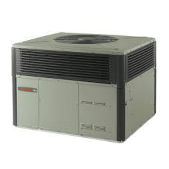
Installer's Guide
Single Packaged Gas/Electric
14 SEER Convertible, 2 — 5 Ton
4YCC4024A1060A
4YCC4030A1070A
4YCC4036A1070A
4YCC4036A1090A
4YCC4042A1060A
4YCC4042A1090A
4YCC4048A1070A
4YCC4048A1090A
4YCC4060A1090A
4YCC4060A1115A
Only qualified personnel should install and service the equipment. The installation, starting up, and servicing of heating, ventilating, and air-conditioning
equipment can be hazardous and requires specific knowledge and training. Improperly installed, adjusted or altered equipment by an unqualified person
could result in death or serious injury. When working on the equipment, observe all precautions in the literature and on the tags, stickers, and labels that
are attached to the equipment.
June 2020
S S A A F F E E T T Y Y W W A A R R N N I I N N G G
1 1 8 8 - - E E B B 3 3 1 1 D D 1 1 - - 1 1 F F - - E E N N
Advertisement
Table of Contents

Related Manuals for Trane 4YCC4024A1060A


Summary of Contents for Trane 4YCC4024A1060A
- Page 1 Installer’s Guide Single Packaged Gas/Electric 14 SEER Convertible, 2 — 5 Ton 4YCC4024A1060A 4YCC4030A1070A 4YCC4036A1070A 4YCC4036A1090A 4YCC4042A1060A 4YCC4042A1090A 4YCC4048A1070A 4YCC4048A1090A 4YCC4060A1090A 4YCC4060A1115A S S A A F F E E T T Y Y W W A A R R N N I I N N G G Only qualified personnel should install and service the equipment.
- Page 2 SAFETY SECTION I I m m p p o o r r t t a a n n t t — This document contains a wiring C C A A U U T T I I O O N N diagram, a parts list, and service information.
-
Page 3: Table Of Contents
Table of Contents Introduction ....... . 4 Electrical Wiring ......23 Field Wiring Diagram . -
Page 4: Introduction
Introduction Read this manual carefully before attempting to install, • Sequence of Operation operate, or perform maintenance on this unit. • Maintenance Installation and maintenance should be performed by S S t t e e p p 1 1 — — I I n n s s p p e e c c t t S S h h i i p p m m e e n n t t qualified service technicians only. -
Page 5: Step 2 - Determine Unit Clearances
Step 2 — Determine Unit Clearances Figure 1. 4YCC4024–4036 1049.02 [41-5/16] Note: The view labeled “Bottom side” represents the base as viewed looking up from underneath the unit. 18-EB31D1-1F-EN... - Page 6 S S t t e e p p 2 2 — — D D e e t t e e r r m m i i n n e e U U n n i i t t C C l l e e a a r r a a n n c c e e s s Figure 2.
- Page 7 S S t t e e p p 2 2 — — D D e e t t e e r r m m i i n n e e U U n n i i t t C C l l e e a a r r a a n n c c e e s s Figure 3.
- Page 8 S S t t e e p p 2 2 — — D D e e t t e e r r m m i i n n e e U U n n i i t t C C l l e e a a r r a a n n c c e e s s Figure 4.
- Page 9 S S t t e e p p 2 2 — — D D e e t t e e r r m m i i n n e e U U n n i i t t C C l l e e a a r r a a n n c c e e s s Figure 5.
- Page 10 S S t t e e p p 2 2 — — D D e e t t e e r r m m i i n n e e U U n n i i t t C C l l e e a a r r a a n n c c e e s s Figure 6.
-
Page 11: Step 3 - Review Location And Recommendation Information
Step 3 — Review Location and Recommendation Information N N o o t t e e : : The unit is shipped for horizontal installation. air. Actual clearances, which appear to be inadequate should be reviewed with a local N N o o t t e e : : During heating operation, avoid supply air below engineer. - Page 12 S S t t e e p p 3 3 — — R R e e v v i i e e w w L L o o c c a a t t i i o o n n a a n n d d R R e e c c o o m m m m e e n n d d a a t t i i o o n n I I n n f f o o r r m m a a t t i i o o n n I I m m p p o o r r t t a a n n t t : : A minimum clearance of 0.0”...
-
Page 13: Step 4 - Unit Installation
Step 4 — Unit Installation N N o o t t e e : : The factory ships this unit for horizontal 5. Flexible duct connectors must be of a flame installation. retardant material. Insulate any ductwork outside of the structure with at least two (2) inches of I I n n s s t t a a l l l l F F l l u u e e H H o o o o d d insulation and weatherproof. - Page 14 S S t t e e p p 4 4 — — U U n n i i t t I I n n s s t t a a l l l l a a t t i i o o n n Figure 7.
- Page 15 S S t t e e p p 4 4 — — U U n n i i t t I I n n s s t t a a l l l l a a t t i i o o n n 4.
- Page 16 S S t t e e p p 4 4 — — U U n n i i t t I I n n s s t t a a l l l l a a t t i i o o n n R R o o o o f f t t o o p p I I n n s s t t a a l l l l a a t t i i o o n n —...
- Page 17 S S t t e e p p 4 4 — — U U n n i i t t I I n n s s t t a a l l l l a a t t i i o o n n Table 3.
- Page 18 S S t t e e p p 4 4 — — U U n n i i t t I I n n s s t t a a l l l l a a t t i i o o n n Table 5.
- Page 19 S S t t e e p p 4 4 — — U U n n i i t t I I n n s s t t a a l l l l a a t t i i o o n n A A t t t t a a c c h h i i n n g g H H o o r r i i z z o o n n t t a a l l D D u u c c t t w w o o r r k k t t o o U U n n i i t t G G a a s s P P i i p p i i n n g g I I n n s s t t a a l l l l a a t t i i o o n n All conditioned air ductwork should be insulated to...
- Page 20 S S t t e e p p 4 4 — — U U n n i i t t I I n n s s t t a a l l l l a a t t i i o o n n Table 7.
- Page 21 S S t t e e p p 4 4 — — U U n n i i t t I I n n s s t t a a l l l l a a t t i i o o n n •...
- Page 22 S S t t e e p p 4 4 — — U U n n i i t t I I n n s s t t a a l l l l a a t t i i o o n n H H i i g g h h A A l l t t i i t t u u d d e e I I n n s s t t a a l l l l a a t t i i o o n n 2000 to 8000 feet elevation, then change the burner orifices to the size listed in Table 4.
-
Page 23: Electrical Wiring
Electrical Wiring W W A A R R N N I I N N G G N N o o t t e e : : Unit must be grounded for ignitor to operate properly. Gas pipe to unit is not an adequate I I N N S S T T A A L L L L A A T T I I O O N N W W A A R R N N I I N N G G —... - Page 24 E E l l e e c c t t r r i i c c a a l l W W i i r r i i n n g g Figure 15. Mounted Disconnect Location Do not short thermostat wires since this will damage the control transformer.
-
Page 25: Field Wiring Diagram
E E l l e e c c t t r r i i c c a a l l W W i i r r i i n n g g Field Wiring Diagram Figure 16. 4YCC4 — Field Wiring Diagram COMMON FAN (GR) (CONSTANT CIRCULATION) -
Page 26: Step 5 - Unit Startup
Step 5 — Unit Startup P P r r e e - - S S t t a a r r t t Q Q u u i i c c k k C C h h e e c c k k l l i i s s t t the normal operating pressures provided in the unit’s SERVICE FACTS. - Page 27 S S t t e e p p 5 5 — — U U n n i i t t S S t t a a r r t t u u p p a. Turn on the electrical power to the unit. 8.
-
Page 28: Sequence Of Operation
Sequence of Operation G G e e n n e e r r a a l l With the thermostat fan switch in the "ON" position, the indoor fan motor (IDM) will continue to run at constant Operation of the system cooling (and optional heating) circulation of 40 –... - Page 29 S S e e q q u u e e n n c c e e o o f f O O p p e e r r a a t t i i o o n n technician check the entire system at least once each 3.
- Page 30 S S e e q q u u e e n n c c e e o o f f O O p p e e r r a a t t i i o o n n Figure 17. 208/230 Volt Speed Taps LOAD PARK INDUCER...
- Page 31 N N o o t t e e s s 18-EB31D1-1F-EN...
- Page 32 About Trane and American Standard Heating and Air Conditioning Trane and American Standard create comfortable, energy efficient indoor environments for residential applications. For more information, please visit www.trane.com or www.americanstandardair.com. The AHRI Certified mark indicates company participation in the AHRI Certification program. For verification of individual certified products, go to ahridirectory.org.
Need help?
Do you have a question about the 4YCC4024A1060A and is the answer not in the manual?
Questions and answers