
Related Manuals for Trane CLCP Euro 25


Summary of Contents for Trane CLCP Euro 25
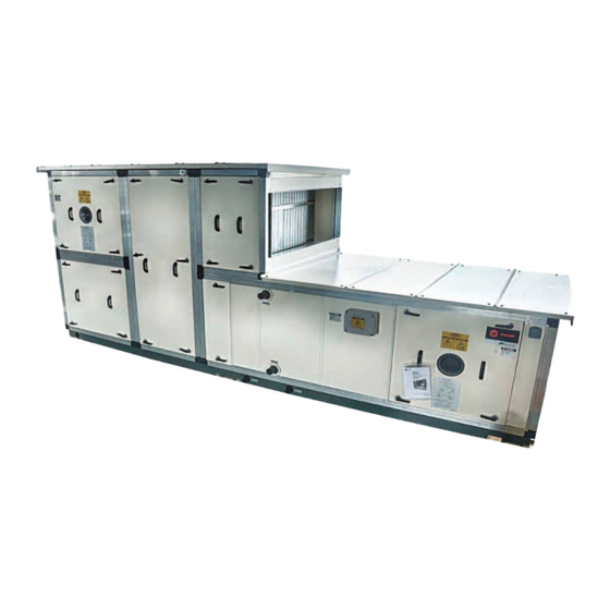
- Page 1 Installation Operation Maintenance Quantum Climate Changer™ Air Handlers Model : CLCP 25, CLCP 50, CLCP Euro Euro Euro Airflow Range : 1000 ~ 65,000 CFM (0.5 ~ 31 m³/s) IND-SVN01A-E4 October 2018...
-
Page 2: Introduction
• When working with or around hazardous chemicals, environment. Trane advocates the responsible handling of all ALWAYS refer to the appropriate MSDS/SDS and refrigerants-including industry replacements for CFCs and OSHA/GHS (Global Harmonized System of Classification HCFCs such as saturated or unsaturated HFCs and HCFCs. - Page 3 Copyright This document and the information in it are the property of Trane, and may not be used or reproduced in whole or in part without written permission. Trane reserves the right to revise this publication at any time, and to make changes to its content without obligation to notify any person of such revision or change.
-
Page 4: Table Of Contents
Table of Contents Introduction ......2 Start-Up ......32 General Information . -
Page 5: General Information
Warranty curved, and airfoil blade designs. To insure fan Trane’s standard warranty covers the equipment. motor assembly stability the unit ships with It does not cover damage due to misuse, lack of shipping brackets located between the fan support maintenance, or failure to comply with the frame. -
Page 6: Model Number Description
Model Number Description CLCPeuro50 - 0030404AM(FDA0900CM)012A1DAAB EG.: WLS01144AXWLS01144AXWLS01144AXE DIGIT DESCRIPTION Base CLCPeuro25 = CLCPeuro-25mm-Eurovent Certified CLCPeuro50 = CLCPeuro-50mm-Eurovent Certified CLCPeuroXP = CLCPeuro-XP(50mm)-Eurovent Certified 003 / 03A/ 004 / 005 / 006 / 007/ 008 / 009/ 010 / 011/ 012 / 013 / 014 / 015/ 016 / 018/ 020 / 022 / 025 / 028 / 030 / 032 / 035 / 038/ 040 / 042/ 045 / 048 / 050 / 055 / 1, 2, 3 Unit Sizes :... -
Page 7: Receiving
Photograph the damages. Do not move or discard damaged freight packaging materials. Notify the Trane sales representative of the damage and arrange for repair. Do not attempt and arrange for repair. Do not attempt to repair the unit without consulting the sales representative. -
Page 8: Rigging And Handling
Always test-lift the unit to determine exact unit balance and stability TRANE Quantum Air Handler are supplied in sections modules, before hoisting it to the installation location. - Page 9 Rigging and Handling APPLICABLE ON ALL SECTION OTHER THAN “SECTION WITH DRAINPAN” Figure 2 APPLICABLE ON SECTION WITH DRAINPAN ONLY Figure 3 Lifting a coil section using a sling rope...
-
Page 10: Roller Movement
Rigging and Handling Forklift Trucks The forks must only be applied under the unit base frame and Figure 6 not against the unit base frame. The lift point should be as near as possible to the centre of gravity (see Figures 4 ,5 and 6). -
Page 11: Unit Placement And Assembly
Unit Placement & Assembly LH/RH Convention Unit handling, LEFT or RIGHT for coil connections, drain etc. Figure 9 is expressed when facing the airflow thru the coil. Foundation Figure 10 When selecting and preparing the unit site, follow these guidelines: Ensure that the site can support the total weight of the unit. -
Page 12: Duct Connections
Unit Placement & Assembly IMPORTANT FAILURE TO PROVIDE A LEVEL PLINTH OR SUPPORT WILL RESULT IN DOORS JAMMING AND AIR LEAKS FROM THE CASING. To minimize noise transmission, insulation material such as cork slabbing (TICO pads) or rubber pad may be placed between the unit base and the foundation (see Figure 12). -
Page 13: Assembly And Installation
Assembly & Installation CLCP & CLCP XP (External Connection) EURO EURO BREAK POINT JOINING METHOD. MODULE TO MODULE BREAK POINT EXTERNAL JOINING (TO BE DONE AT JOB SITE) FOR CLCP 25mm FOR CLCP 50mm... - Page 14 Assembly & Installation CLCP 25 Breakpoint - Frame to Frame EURO (OMS C0325_B) CLCP 25 - Break Point Frame to Frame Joining EURO...
- Page 15 Assembly & Installation CLCP 25 Breakpoint - Panel to Frame EURO (OMS C0326_B) CLCP 25 - Break Point Panel to Frame Joining EURO...
- Page 16 Assembly & Installation CLCP 50 Breakpoint - Frame to Frame EURO CLCP 50 - Break Point Frame to Frame Joining EURO...
- Page 17 Assembly & Installation CLCP 50 Breakpoint - Panel to Frame EURO CLCP 50 - Break Point Panel to Frame Joining EURO...
- Page 18 Assembly & Installation CLCP CLCP XP Paneling EURO EURO...
- Page 19 Assembly & Installation CLCP XP Breakpoint EURO ASSEMBLY & INSTALLATION CLCP XP BREAKPOINT – INTERNAL JOINT (TYPE1) EURO...
- Page 20 Assembly & Installation CLCP XP Breakpoint EURO ASSEMBLY & INSTALLATION CLCP XP – STANDARD SECTION TO WIDER SECTION EURO INTERNAL JOINT (TYPE 2)
- Page 21 Assembly & Installation CLCP XP Breakpoint EURO ASSEMBLY & INSTALLATION CLCP XP – STANDARD SECTION TO WIDER SECTION EURO INTERNAL JOINT (TYPE 3)
- Page 22 Assembly & Installation CLCP XP CKD At Jobsite EURO...
- Page 23 Assembly & Installation CLCP...
- Page 24 Assembly & Installation CLCP...
- Page 25 Assembly & Installation CLCP Removing & Replacing a motor (CLCP 003 – 015) Removing shipping bracket (non-drive side) (CLCP 003 – 035) Apply Silicone along panel parameters prior to installing back the panel after removing shipping bracket...
-
Page 26: Piping And Connection
Piping – Condensate Drain Pan Unit With More Than 1 Drain Pan Connection With the Trane QuantumTM Air Handler, each module can be ordered with or without a drain pan. When more than one On cooling section(s) the drain pan should always be... - Page 27 Piping and Connection Chilled Water Piping – Coil Connection Figure 15 General Coil Piping Recommendation Refer to Figure 15 & 17 Typical Piping for Water Coil. for typical cooling / heating and steam coil piping. Proper installation, piping and trapping is necessary to assure satisfactory coil operation and to prevent operational damage.
- Page 28 Piping and Connections Steam Coil Piping Type A, AA Steam • Use float and thermostatic traps with atmospheric pressure gravity condensate return, with automatic Coil control or where the possibility of low-pressure supply steam exists. These are for central system, industrial and process •...
- Page 29 All compressors have a Refrigerant Charge Limit (RCL) that must not be exceeded. Since the RCL and pressure drop are in direct conflict with each other, Trane recommends that the General refrigerant Piping liquid line be sized as small as possible, while maintaining a Recommendations low enough pressure drop to ensure 5ºF(3ºC) of subcooling at...
- Page 30 Piping and Connections Figure 18 Typical Piping for Refrigerant Coil CAUTION To avoid equipment malfunction, use care when brazing or soldering so that distributor tubing is not restricted or blocked. To braze Thermostatic Expansion Valves (TXV) avoid direct flame (figure 19) to the valve body and avoid excessive heat on diaphragm.
- Page 31 Piping and Connection Factory Supplied OFF Set Type Coil Flange Installation CLCP: 030 – 050 (For Double Coil In Single casing, LL & WL, 4 Row Only) 1. Flange Socket Weld (Standard) 2. Flange Socket Weld (Offset Type)
-
Page 32: Start-Up
Consult a qualified or by a blower. water treatment specialist to determine if water treatment is required. The Trane Company assumes no Inspect the entire motor for rust and corrosion. responsibility for equipment damage caused by Lubricate the motor as instructed in the section titled “Periodic... - Page 33 Start-Up Excessive Vibration EXCESSIVE VIBRATION MUST BE CORRECTED TO PREVENT BEARING AND SHAFT DAMAGE. SEE THE SECTION TITLED “TROBLESHOOTING” FOR DETAILS ON THE COMMON CAUSE FOR VIBRATION. Determine Fan RPM Fan RPM can be determined by using a strobe-type tachometer, or revolution counter. Sheave Alignment Align the fan motor sheaves by using a straightedge.
-
Page 34: Maintenance
Maintenance Periodic Maintenance Checklist Every Year The following checklist describes the suggested maintenance Inspect the unit casing for corrosion. If damage is found, schedule to maintain proper operation of the unit. Detailed clean and re-paint the surface with a rust-resistant primer procedures for owner operator maintenance checks are given and vinyl chlorinated lacquer. -
Page 35: Maintenance Plan
Maintenance Maintenance Plan The following table (see Table 1) gives recommended maintenance intervals for the CLCP unit. Intervals are based upon normal running conditions, in a moderate climate, and assuming 24 hour running. Units operating outside these guidelines may require shorter or longer maintenance intervals. - Page 36 Inspect periodically for excessive vibration or temperature. Operating conditions will vary the frequency of inspection and lubrication. Contact the motor manufacturer or Trane for 2. Fan lubrication instruction. Most smaller frame motors come If the fan/motor assembly is going to be stored for two weeks...
- Page 37 Maintenance 4. Air Filters 6. Coil Cleaning Appendix B provides filter size, type and quantity. To replace Steam, hot water and chilled water coils should be kept clean throwaway filters, install new filters with the directional arrows to maintain maximum performance. lf fins become dirty, clean pointing in direction of airflow.
- Page 38 Maintenance Check following: Direct expansion coils Worn groove sidewalls, "Dishing" should not exceed Never use hot water or steam to clean these coils. During 1/32"(0.8mm) for individual belts. With a banded belt, normal operation, the fin block must not ice up. If this occurs, dishing should not exceed 1/ 64"(0.4mm).
- Page 39 Maintenance 6. Check pulley alignment. Figure 18 • Place a straight edge across pulleys faces to correct Sheave Alignment alignment. • Check parallel position of shafts and correct alignment or grooves. • Note: Store belts in a cool, dry place out of direct sunlight.
- Page 40 Maintenance...
-
Page 41: Trouble Analysis
Use the tables in this section to assist in identifying the cause or causes of a malfunction in Air Handler operation. The column header RECOMMENDED ACTION will suggest repair procedures. Note: These tables are intended as a diagnostic aid only. For detailed repair procedures, contact your local Trane Service Company. - Page 42 Trouble Analysis...
-
Page 43: Pulley And Belt
Trouble Analysis Pulley and Belt... -
Page 44: Appendix A - Fan Arrangement
Appendix A – Fan and Arrangement Fan Discharge Arrangement... -
Page 45: Appendix B - Filter Layout & Quantity
Appendix B – Filter Layout and Quantity Filter Dimension (Nominal) and Arrangement Flat, Bag, Cartridge Air Filter 6110-3130_2(page1) - Page 46 Appendix B – Filter Layout and Quantity Filter Dimension (Nominal) and Arrangement Flat, Bag, Cartridge Air Filter 6110-3130_2(page2)
- Page 47 Appendix B – Filter Layout and Quantity Filter Dimension (Nominal) and Arrangement High Capacity Air Filter (Angle Filter) 6110-3286_A...
- Page 48 Appendix B – Filter Layout and Quantity Filter Dimension (Nominal) and Arrangement HEPA (AstroCel I-HCX) Filter 6110-3323_A...
- Page 49 Appendix B – Filter Layout and Quantity Filter Dimension (Nominal) and Arrangement HEPA (AstroCel-VXL) Filter 6112-1853...
- Page 50 Appendix B – Filter Layout and Quantity Filter Dimension (Nominal) and Arrangement HEPA (AstroCel-VXL) Filter...
-
Page 51: Typical Motor Wiring Diagram
Typical Motor Wiring Diagram... -
Page 52: Service Light / Door Switch Wiring
Service Light and Door Switch Wiring... -
Page 53: Factory Installed Vfd Tr200 Wiring & Setting
Factory Installed VFD-TR200 (Wiring & Setting) - Page 54 Factory Installed VFD-TR200 (Wiring & Setting) TR200 BASIC SETTING_OPEN LOOP...
-
Page 55: Contract And Training
Please refer to your nearest office. ln no event shall Trane be liable for any incidental or consequential damages resulting from the use, misuse or... -
Page 56: Pre-Start Up Checklist
Pre-Start Up Checklist... - Page 57 Pre-Start Up Checklist...
- Page 58 Ingersoll Rand (NYSE:IR) advances the quality of life by creating comfortable, sustainable and efficient environments. Our people and ou r family of brands—including Club Car®, Ingersoll Rand®, Thermo King® and Trane®—work together to enhance the quality and comfort of air in homes and buildings; transport and protect food and perishables; and increase industrial productivity and efficiency.
Need help?
Do you have a question about the CLCP Euro 25 and is the answer not in the manual?
Questions and answers