Table of Contents
Advertisement
Quick Links
Advertisement
Table of Contents

Related Manuals for IKUSI 3854


Summary of Contents for IKUSI 3854
- Page 1 Web interface user guide MHD-201 REF. 3854 High-definition modulator...
- Page 3 Index Introduction About this Manual Product Description Web interface connection Ethernet configuration by application IKUSI HEADEND DISCOVERY Ethernet manually configuration General Configuration Main Menu Identification Local configuration Network configuration Web access password Save/Restore configuration Upgrade Restart Signals Adjustment Services Input settings...
-
Page 4: About This Manual
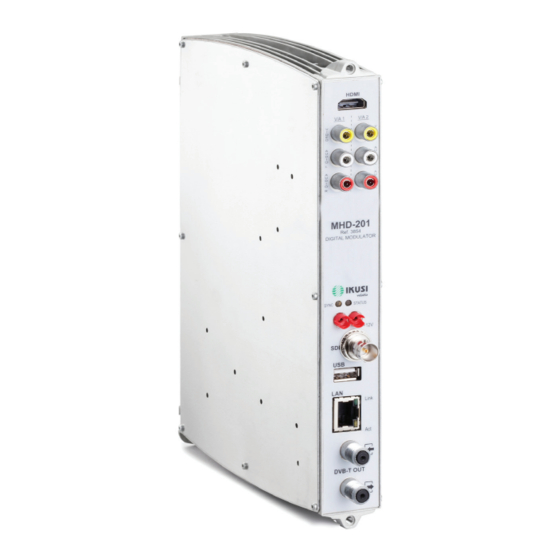
This configuration manual is a practical reference guide. For the correct use and installation of the MHD-201, it is essential to read the corresponding user manual (please see www.ikusi.tv for the manual). Product Description The MHD-201 is a standalone modulator that can process different Video and Audio for- mats, to create a high-definition COFDM channel. -
Page 5: Web Interface Connection
Ethernet configuration by application: Download the IKUSI HEADEND DISCOVERY application available on the website (http://customerarea.ikusi.tv). In the window we will find the model, the MAC number, serial number and manufacturing firmware version to access the interface of this module simply click on the SET button. In the home page the USERNAME AND PASSWORD fields appear, enter “admin”... - Page 6 Web Interface Connection Ethernet manually configuration: Access the PC’S TCP/IP Settings and configure the following parameters: * PC’S /IP Address: 192.168.1.1 * Subnet Mask: 255.255.255.0 Connect the PC to the LAN port (RJ-45) of the MHD-201 unit (position 1 in the diagram below).
-
Page 7: General Configuration
General Configuration General Configuration Main menu 1-Main menu 2-Submenus 3-Work area 4-Language selection 5-Save configuration To explore the different menus, select each option in the menus area (position 1 in the diagram above). Depending on the options available in each menu, there will be one or various submenus (position 2 in the diagram above). -
Page 8: Local Configuration
General Configuration Identification Select the GENERAL menu and then the CONFIGURATION submenu. Access the IDENTIFICATION menu. The IDENTIFICATION tab provides configuration data identifying the MHD-201 unit. MODEL: The name of the unit. This information cannot be modified. SERIAL NUMBER: Displays the manufacturers’ serial number identifying the unit. This information cannot be modified. -
Page 9: Network Configuration
General Configuration TIME ZONE: Set the time zone of the country in which the unit is operating. CURRENT DATE AND TIME: Shows the hour, date and format (Date: YYYY-MM- DD; Time: HH:MM). Once you have configured the data, you can save the changes by clicking on SAVE on the bottom part of the tab. -
Page 10: Save/Restore Configuration
General Configuration OLD PASSWORD: Enter the current password. NEW PASSWORD: Enter the new password. CONFIRM NEW PASSWORD: Re-enter the new password. Once you have configured the data, you can save your changes by clicking on SAVE in the lower part of the tab. Save/Restore configuration Select the GENERAL menu and then the SAVE/RESTORE menu. - Page 11 To execute and load the new firmware click on the UPDATE button. NOTE The firmware update file has to be stored on the PC’s hard drive (it can be down- loaded from http://customerarea.ikusi.tv).
- Page 12 General Configuration Resart Select the GENERAL menu and then the RESTART submenu. Click on the RESTART button. The RESTART configuration file can now be used to restart the MHD-201 unit. Once you have restarted the unit, the home page will appear again. MHD-201...
- Page 13 Settings Settings Services Select the SETTINGS menu and then the SERVICES submenu. Specify the parameters inside the SELECTION submenu: INPUT TYPE: Specify one of the five possible combinations. OUTPUT TYPE: DVB-T and IP Specify the parameters within the INPUT SETTINGS submenu: INPUT ASPECT RATIO: 16/9 or 4/3 The INPUT 1 tab reports on the status of the analogue AV TV input connected to the AV1 input, allowing you to modify how the audio and video components are processed.
- Page 14 Settings Within the OUTPUT SETTINGS submenu, specify the following parameters: BRIGHTNESS (1-255): Allows you to set the image’s brightness within a 1 to 255 range of values. You can enter a value or raise or lower the value unit-by-unit using the buttons on the right of the value field.
- Page 15 Settings LOW LATENCY: It reduces the codification time for those applications where the reaction time is important (i.e. cameras). The selection of the mode low latency, has a significant decrease in terms of codification efficiency and images (with much move- ment) quality.
- Page 16 Settings DVB-T Output Select the SETTINGS menu and then the DVB-T OUTPUT submenu. Specify the following parameters in the DVB-T submenu: CHANNEL: Allows you to select and modify the output channel. FREQUENCY: States the output frequency of the current radiofrequency carrier and allows you to modify its value.
- Page 17 Settings NETWORK NAME: Allows you to assign a name to the network. PROVIDER: Allows you to specify the name of the service provider. NID: Allows you to assign a value to the network identifier. TSID: Allows you to assign a value to the transport stream (or TS) identifier. NOTE When configuring a headend with 2 or more units, the TSID value must be diffe- rent in each unit.
- Page 18 USB player IP Output Select the SETTINGS menu and then the IP OUTPUT submenu. Specify the following parameters in the IP submenu: PROTOCOL: The drop down menu offers two options : UDP and UDP/RTP. UDP is a transport protocol. Time To Live: Is a parameter used to restrict the multicasting range. QoS: Quality of Service.
- Page 19 Status STATUS: Tells you the status of the output services NUMBER OF SERVICES: Reports the number of services. OUTPUT BITRATE: Tells you the speed of the binary data at the unit’s output. USB Player Select the SETTINGS menu and then the USB PLAYER submenu. Within the FILE PLA- YBACK submenu, the Status section provides the following information: USB INSERTED: Tells you whether or not there is a pen drive connected to the unit.
- Page 20 Status Status Select the STATUS menu. The STATUS tabs provide all the information on the statuses of the inputs and outputs, and the other general parameters of the unit (alarms, temperature, services, etc). Access the INPUT tab. INPUT 1 AND INPUT 2: VIDEO: shows whether there is a valid video signal at the input.
- Page 21 Reports Access the GENERAL tab. GENERAL: AVAILABLE VALUES: OK/ERROR TIME WORKING: Displays an error message if a hardware problem has been detected. HW STATUS: Displays an error message if an HD input has been inserted in the SD input. IN STATUS: Displays an error message if there is any problem at the DVB-T output, such as an overflow.
- Page 22 Status Reports Configuration Select the REPORTS menu and then the CONFIGURATION submenu. The general report provides information on the general configuration of the unit, as perfor- med in the following submenu tabs:...
- Page 23 Status Logs Select the REPORTS menu and then the SYSTEM LOGS submenu.
- Page 24 Ángel Iglesias, S.A. Paseo Miramón, 170 20009 San Sebastián, Spain Tel. +34 943 44 88 00 Fax +34 943 44 88 20 ikusi@ikusi.com www.ikusi.com...
Need help?
Do you have a question about the 3854 and is the answer not in the manual?
Questions and answers