Table of Contents
Advertisement
Advertisement
Table of Contents

Related Manuals for IKUSI HTL-STC


Summary of Contents for IKUSI HTL-STC
- Page 1 Web Interface guide HTL-STC / HTL-TRX Ref. 3860 Ref. 3861...
-
Page 2: Table Of Contents
Index 1. Introduction ..........................4 1.1 General safety instructions................4 1.2 Installation environment recommendations .......... 5 2. General description......................5 3. Basic installation ........................6 3.1 Headend connection ..................6 3.2 Definition of the master module ..............7 4. Setup Wizard ........................... 9 4.1. -
Page 3: Introduction
1. Introduction To ensure the correct use and installation of the headend, it is necessary to read the user manuals and the installation manuals of the modules included in their own packages. 1.1 General safety instructions Read all of this user manual carefully before plugging in the unit. Always have these instructions to hand during installation. -
Page 4: Installation Environment Recommendations
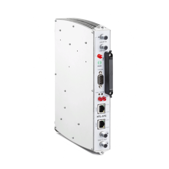
This headend station is designed for broadcasting DVB-T or DVB-C signals based on open or encrypted DVB-S/S2/T/T2/C signals, and is made up of the following elements: • HTL-STC (Ref. 3860): DVB-S/S2/T/T2/C to DVB-T/C transmodulator • HTL-TRX (Ref. 3861): DVB-S/S2/T/T2/C to DVB-T/C transmodulator, MPEG4 to MPEG2 transcoder... -
Page 5: Basic Installation
An HTL-TRX transmodulator/transcoder modules offers the same transmodulation functionalities as an HTL-STC, allowing also to transcode up to four MPEG4 (1080i or 576i) services to MPEG2 576i with a maximun of four audio channels in total (AC3/AC3+ to MPEG1 Layer II). -
Page 6: Definition Of The Master Module
Use IKUSI HEADEND DISCOVERY application to communicate with the modules without modifying manually the network configuration of your pc. You can download the IKUSI HEADEND DISCOVERY aplication from www.ikusi.tv web page. NOTE: You must use IKUSI HEADEND DISCOVERY version 1.8.4 or higher. - Page 7 By default, the language of the web interface is the same than the one used by the browser. If you want to change it, choose in the icon, the flag related with the desired language. Accept Enter the folowing data, User: Admin Password: admin. Push button.
-
Page 8: Setup Wizard
4. Setup Wizard Setup wizard will guide you simply and quickly through set-up. It will be launched automatically the first time the headend is configured. To access to wizard subsequently, you can do it from the Advanced adjustment menu of the headend, selecting Wizard option. Wizard will open indicating step by step the actions that must be done. -
Page 9: Step 2: Global Configuration
4.2 Step 2: Global configuration A window as the following one will open: In this window you can configure the following parameters: • TV Configuration: choosing an specific country, the headend will be configured respecting the particularities of the TV standards of that country (RF frequency plan, modulation scheme, LCN descriptors, etc). -
Page 10: Step 3: Output Channel Configuration
4.3 Step 3: Output channel configuration This screen allows to select the output RF channels where the contents will be transmitted. Setup wizard shows a frequency plan with all the available channels. By default, setup wizard proposes the lowest channels. To change that selection, move the channels manually, dragging and dropping them in an empty channel. - Page 11 Next Push button to accept the channel distribution.
-
Page 12: Step 4: Satellite
4.4 Step 4: Satellite This screen allows to configure the parameters related with the used satellite installation. It only appears when RF Input has been selected as DVB-S/S2 in the step 2. In other case, setup wizard skips this step and goes directly to step 5. When the satellite signal is delivered to the HTL through a multiswitch, select Enable DISEqC: DiSEqC ON, introducing the number of inputs of the multiswitch in Number of polarities (in the example, 4 inputs, i.e., a complete satellite). -
Page 13: Step 5: Service Management
4.5 Step 5: Service management This screen allows to select which services must be received, and it is different depending on the value of RF Input that has been configured in step 2. Below, the two types of screens are described. 4.5.1 Satellite input case In the case you have configured DVB-S/S2 as RF input in the step 2, a window as the following one will be displayed:... - Page 14 Repeat the same process with all the satellite transponders. In this example, the headend is formed by 2 HTL-TRX modules, therefore you can receive up to 4 satellite transponders. If you want to remove any of the transponders, push button.
-
Page 15: Terrestrial/Cable Input Case
After that, select the services that are going to be included in the output channel lineup. To select a specific service, click in the check box next to that service. If you want to select all the services of a transponder, push button. -
Page 16: Step 6: Service Configuration
The headend will scan the input signal automatically. A progress bar will be displayed, indicating the percentage of the scanning that has been performed. When the scanning finish, the information of the detected multiplexes will be displayed. Select the desired services clicking in the check box next to those services. - Page 17 You can change the distribution mode of the services according to the audios. To do that, push button or over icon. Audio configuration box will open. The headend has two working modes, disaggregated languages or aggregated languages. When disaggregated languages mode is selected, in the case a multi-language service, one service will be...
-
Page 18: Step 7: Lcn, Sid, Output Name Configuration
generated for each language. The dissaggregation is done at logical level, i.e., the used bandwidth is the same as the used with a single service conveying all the languages; however the TV is detecting several independent services. Therefore, the final user can select the desired language simply changing the channel. -
Page 19: Step 8: Search For Supported Configuration
If you want it, you can edit those fields. Also, you can remove any of the the services, pushing button . Send To send the configuration that has been defined through setup wizard, push button. A confirmation window will open, informing that the configuration will be stored in the modules. Continue If you agree, push button. -
Page 20: Step 9: Confirmation Of The New Service Configuration
When the process ends, the configuration will be stored in the modules and setup wizard will go to step 9. 4.9 Step 9: Confirmation of the new service configuration In the final step, a summarize window will be displayed, with a list of the services that forms the selected channel lineup, indicating in which RF channel will be transmitted each one. - Page 21 If you want it, you can sustitute that RF channel by other of the channels generated by the module that is processing that service. Close To finish with setup wizard, push button. Browser will go automatically to the Advanced adjustment menu. From there, you can relaunch setup wizard when you want, selecting Wizard option.
-
Page 22: Manual Configuration
5. Manual configuration HTL headend allows a quick and agile configuration through the Installation Wizard. However, there are situation where this configuration must be customized. In those cases, advanced interface available options must be used. In that interface, we will also find additional information about the status of the headend. - Page 23 USE DHCP: Enable the checkbox for the DHCP server to automatically assign an IP address. Disable the checkbox to manually enter the IP address, the netmask and the preset gateway. IP ADDRESS: Enter the IP address if DHCP is not enabled. NETMASK: Enter the netmask if DHCP is not enabled.
- Page 24 MULTISWITCH POSITION, VOLTAGE AND TONE SATELLITE: Designation of the multiswitch input signal for identification in subsequent configurations. IKUSI recommends identifying the type of satellite, polarity and signal band. POLARITY: Click on the drop-down list to select the vertical or horizontal polarity.
- Page 25 Headend Firmware Add firmware file... To update the headend with a new firmware, push button to select the file of that new firmware. Configuration Backup Used to create a backup of the current configuration of the station or apply an update. Configuration report: Used to save the backup copy in the location chosen by the user or download it to another station.
-
Page 26: Un)Register Modules
Clicking on any of the boxes will activate the “apply default configuration”, moving on to the reset confirmation window. Enabling the box to the left of the title will select all the headend modules. 5.1. Headend 5.1.2 (Un)Register Modules All the modules which are connected to the IKUNET bus must appear on the screen inside a cell headed by the type of module and the function it represents within the headend (slave). -
Page 27: Input And Output Configuration
5.1. Headend 5.1.3 Input and Output Configuration Inputs The Inputs tab shows the following parameters: NAME: Name to identify each module. MODEL: Module type designation. RF Input: Dropdown list that allows to choose the behaviour of the input connectors. Select “2 Inputs”... - Page 28 MULTISWITCH: It allows to select the multiswitch signal (or the LNB signal) to be received. IF BAND: Low or High. STATUS: It allows to enable or disable any of the two inputs of the module. TRANSPONDER FREQUENCY: It allows to select the frequency value of the transponder to be received.
- Page 29 This tab allow to access to the information of the CAM. The following infomation related to each CAM is displayed: NAME: Identification of the module in which the CAM is inserted. MODEL: Model of the module in which the CAM is inserted. MAX ALLOWED PIDs: Maximum number of services and elementary streams (PIDS) that can be decrypted by that CAM.
- Page 30 OUTPUT: Identifier of the output that is being described (Output 1 or Output 2). FRECUENCY: Frequency of the output carrier. BITRATEMAX: Maximum bit rate value supported by the output carrier. Depends on the output type and the used values for its setting. FREE SPACE: It is the value of the unused space respect to the maximum bit rate described in the previous point, expressed in percentage.
-
Page 31: Headend Networks
Finally, when the output signal is DVB-C, the displayed parameters will be: STATUS: It allows to enable or disable any of the two outputs of the module. FREQUENCY: It allows to select the frequency value of the carrier to be generated. SYMBOLRATE: It allows to select the symbol rate the symbol rate of the output carrier to be generated. - Page 32 NAME: Shows the proposed network name. NID: Shows the network identifier. ONID: It allows to select the value that will be included as original network identifier in all multiplex that forms the network. AUTOMATIC SERVICES LIST: Activate the box to include a service_list_descriptor in the NIT, generated by the master module and based on the services available at the headend station output.
-
Page 33: Headend Module List
5.1. Headend 5.1.5 Headend modules list This section contains all the information on the main parameters of the headend station. The first window shows the following details: NAME: Name to identify each module. MODEL: Module type designation. MAC: Number which identifies each module for the network connection. ALARM/STATUS: Operation alarm in the module. -
Page 34: Detailed Status
5.1. Headend 5.1.6 Detailed Status This section contains all the information on the status of the headend modules. The screen shows the input and output parameters corresponding to each module, along with the alarms and CAM details. -
Page 35: Headend Services
5.2. Headend Services Click on the drop-down list to access the following options: Click on the drop-down list to access the following options: LCN OFFSET: Defines the LCN position of the first service: HD TVs: If it is enabled, it indicates that there are HD TVs in the current premises. This parameter will be used by the headend to activate the transcoding when the TV contents are HD and the TVs are SD. - Page 36 SUBTITLES: It allows to block or to not block, to decript or to not decrypt, the subititling information of the source signal. DATA: It allows to block or to not block, to decript or to not decrypt, the data information of the source signal.
-
Page 37: System Logs
5.3. System Logs This query screen is used to obtain an overview of all incidents in the status of the headend in chronological order. -
Page 38: Ugrade Report
5.4. Upgrade Report This screen is used to see if all the firmware upgrades have been completed successfully. 5.5. Select Language Used to select the application language. -
Page 39: Exit
5.6. Exit Used to leave the interface, returning to the home screen. Equipment recycling RECYCLING OF ELECTRICAL AND ELECTRONIC EQUIPMENT (Applicable in the European Union and in European countries with selective waste collection systems) This symbol on your equipment or its packaging indicates that this product cannot be treated as general domestic waste and must be handed in at the corresponding point of collection for electric and electronic equipment. - Page 40 Paseo Miramón, 170 20014 San Sebastián Gipuzkoa, España Tel.: +34 943 44 89 44 Fax: +34 943 44 88 20 television@ikusi.com www.ikusi.tv...
Need help?
Do you have a question about the HTL-STC and is the answer not in the manual?
Questions and answers