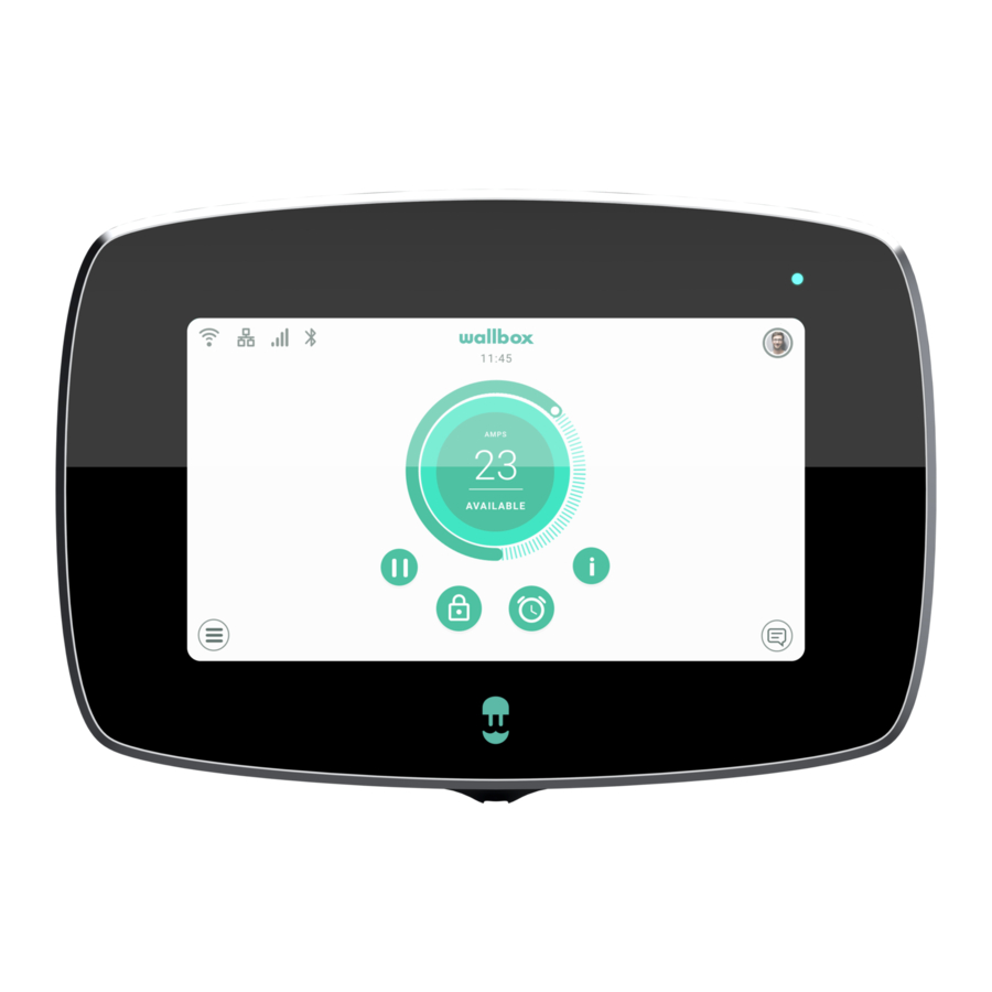
Wallbox COMMANDER 2 Service Manual
Hide thumbs
Also See for COMMANDER 2:
- Installation manual (112 pages) ,
- User manual (50 pages) ,
- Installation and user manual (7 pages)
Advertisement
Quick Links
Advertisement

Summary of Contents for Wallbox COMMANDER 2
- Page 1 COMMANDER 2 Service Manual...
- Page 2 INDEX Important Information Required Materials Front Cover Replacement Removing the Front Cover Attaching the new Front Cover Replacement of the Power Board Removing the old Power Board Attaching the new Power Board CPU Placement Removing the CPU Attaching the CPU Service...
- Page 3 Important Information Introduction and Scope The purpose of this document is to describe the process of replacing service parts of the Commander 2 charger’s hardware system. Intent of this service manual is to lend a hand to our service partners in replacing the service parts.
-
Page 4: Required Materials
Required Materials Torx T9 Star Commander 2 Spare part to be replaced: Screwdriver Screwdriver Opening Tool Control Board + Cover, Power Board... -
Page 5: Front Cover Replacement
Front Cover Replacement The Control board of the Commander 2 charger is enclosed within the front cover of the charger. The Control board consists of the following components: • Wireless Communication System: BLE, Wi-fi, RFID reader • Microcontroller unit • CPU... - Page 6 Attaching the new Front cover Carefully attach the communications cable to Be cautious and ensure that the CPU and the connector on the Control board. the RFID card on the Control board remains undamaged while replacing the front cover Position the top clip points of the front cover Place the sticker with the new Serial Number on the charger body.
- Page 7 Replacement of the Power Board The Power board of the Commander 2 charger is enclosed within the plastic body of the charger. The Power board consists of the following components: • Power Supply Unit • Wired Communications: MID, Power Sharing, Control pilot, etc.
- Page 8 Disconnect the input power cables by using a Gently push the levers on the power star screwdriver and control pilot connectors with your screwdriver to disconnect the conductors of the charging cable. Unscrew the 4 screws that hold the Power Keep the old Power board aside for return or board to the body and save them for later disposal.
- Page 9 Attaching the new Power board Fit the replacement Power board in place and Connect all the conductors to the Power fix it to the body with the 4 screws that were board in the exact same position as they previously removed and kept aside. were before.
- Page 10 Removing the CPU The Control board of the Commander 2 charger is enclosed within the front cover of the charger. Turn off the power supply to the charger. Open the front cover of the charger by performing the steps mentioned in the Removing the old Front cover section above.
- Page 11 Carefully remove the CPU by gently pulling its top part towards you. Attaching the CPU To attach the CPU on the Control board, perform the following steps: Identify the insertion mark on the edge of the Hold the other end of the CPU and place it CPU.
- Page 12 +353 14 854 347 +351 308 801 440 +46 852503203 Deutschland Italia Österreich United Kingdom +49 69 96759775 +39 011 1962 2461 +43 720882116 +44 20 3318 3779 Nederland España +31 20 808 0847 +34 932 20 95 75 www.wallbox.com service@wallbox.com...


Need help?
Do you have a question about the COMMANDER 2 and is the answer not in the manual?
Questions and answers