
Related Manuals for domi LGMF1613


Summary of Contents for domi LGMF1613
- Page 1 14'×20' Metal Gazebo ASSEMBLY MANUAL MODEL#: LGMF1613 Missing part? Damaged? Contact us via email at service@domioutdoorliving.com www.domioutdoorliving.com © Copyright 2022-2024 Domi Outdoor Living LLC. All Rights Reserved.
- Page 4 L x4 L1 x2 2080 A x4 Mb x4 Ma x4 M x4 2080 2245 B x2 N x2 2245 2000 C x4 N1 x4 2220 1877 C1 x4 N2 x2 1102 1896 C2 x2 P x2 1183 1896 C3 x2 P1 x2 1431 2000...
- Page 5 U6 x3 U7 x3 W1 x2 W2 x2 W3 x2 W4 x2 W5 x2 W6 x2 W7 x2 W8 x2 X1 x2 X2 x2 X3 x2 X4 x2 X5 x2 X6 x2 X7 x2 X8 x2 X9 x2 X10 x2 X11 x2 X12 x2 Y x4...
- Page 6 (1) Attach Part #L to Part #A with 3 Bolts 1#. (2) Attach Part #L1 to Part #B with 4 Bolts 1#. (3) Repeat the above procedures to assemble the other 3 Part #A and 1 Part #B.
- Page 7 (1) Insert Part #F into Part #D and secure with 2 Bolts 1#, insert the other side of Part #F into Part #C and secure with 2 Bolts 1#. (2) Connect Part #D and Part #C through Part #F. It’s a normal situation that there’s a gap between the 2 beams, please use silicone sealant (part #H2) and bracket #H to affix the gap.(See P8)
-
Page 8: Side View
(1) ①Install Part #C2 and Part #C1 onto Part #C with Bolts 1#. (Part #C2 on top and Part #C1 on the bottom) ②Install Part #D2 and Part #D1 onto Part #D with Bolts 1#. (Part #D2 on top and Part #D1 on the bottom) (Please refer to the front and side view diagrams.) Side View... - Page 9 (1) Insert Part #F into Part #D and secure with 2 Bolts 1#, insert the other side of Part #F into Part #E and secure with 2 Bolts 1#. (2) Insert Part #F into Part #E and secure with 2 Bolts 1#, insert the other side of Part #F into Part #C and secure with 2 Bolts 1#.
- Page 10 Side view (1) Install Part #C3/#D3/#E2a/#E2b and Part #C1/#D1/#E1a/#E1b onto Part #D/#E/#C with Bolts 1#. (Please refer to the front and side view diagrams.) Front view (2) Repeat the above procedures to assemble the other Part #D/#E/#C.
- Page 11 (2) Connect Part #C and Part #D to Part #A with 4 Bolts 2#. (From Inside) (1) Connect Part #D and Part #C to Part #A with 4 Bolts 3#. (From Outside) (3) Connect Part #E to Part #B with 6 Bolts 2#. (From Inside) (4) Repeat the above procedures to assemble the other 3 sides.
- Page 12 (1) Affix Part #J1 and Part #J2 to the frame with 8 Bolts 1#. (2) Repeat the above procedures to assemble the other 3 corners. Tighten all bolts.
- Page 13 (1) Cover the corner with Part #G. Secure with 4 Screws 9#. (2) Repeat the above procedures to assemble the other 3 corners. (3) Cover Part #H over the 4 connection points as shown in ②. Secure with 2 Screws 9# from top to bottom and 1 Screw 8# from bottom to top.
- Page 14 After finish inserting hooks into tracks, use part #H1 & bolt #8 to lock them. (1) Put 8 hooks to each side wall track(Part C&D). (2) Put 8 hooks to each side wall track Part C and 4 hooks to side wall track Part E. (3) Put 4 hooks to each side wall track Part E and 8 hooks to side wall track Part D.
- Page 15 Assemble the 4 Corner Roof Bars: (1) Connect Part #Ma and Part #Mb with 2 Bolts 2# . (2) Repeat the above procedures to assemble the other 3 corner roof bars.
-
Page 16: Vertical View
Vertical view (1) Please have a freestanding ladder ready at the center of the gazebo. (2) Place 4 Part #M on the 4 corners of Part #K. Secure with 8 Bolts 1#. (from bottom to top) ATTENTION: You can also finish this step on the ground and then lift 4 corner roof bars and inside roof connector #K to the top together. - Page 17 Vertical view Outside view (1) Place 2 Part #N2 on part #K. Secure with 2 Bolts 1# (from bottom to top). (2) Place 2 Part #N2 on 2 Part #B; Secure with 4 Bolts 1#.
- Page 18 Vertical view Inside view (1) Place 4 Part #N1 on Part #K. Secure with 8 Bolts 1# (from bottom to top). (2) Connect 4 Part #N1with the Beam by using 8 Bolts 1#.
- Page 19 Vertical view Inside view (1) Place 2 Part #N on Part #K. Secure with 2 Bolts 1# (from bottom to top). (2) Connect 2 Part #N with the Beam by using 4 Bolts 1#.
- Page 20 Vertical view (1) Attach Part #Q1 and Part #Q2 to Part #N2; Secure with Bolt 1#. (2) Repeat the above procedures to assemble the opposite side. Inside view...
- Page 21 Vertical view (1) Attach Part #P and Part #Q2/Q1 to Part #M; Secure with Part #R and Bolt 1#. (2) Repeat the above procedures to assemble the other 3 corners. Inside view...
- Page 22 (1) Attach Part #P1 to the frame and use 2 Screws 11# & 1 Screw 1# to fix. (2) Attach Part #Q3 & #Q4 to the frame and use 4 Screws 11# & 3 Screws to fix. (3) Repeat the above procedures to assemble the opposite side.
- Page 23 Place Part #K to the top frame and use 5 Screws 1# to fix.
- Page 24 (1) Attach 3 Part #U6 (2) Attach 3 Part #U6 to the frame and use to the frame and use 3 Screws 1# to fix. 3 Screws 1# to fix.
- Page 25 Cover Part #Z & #Z1 & #Z2 & #Z3 & #Z4 to the roof panels...
- Page 26 If you cannot install roof panel #V6, #V, or #V7, please push the outside roof cover up and try to insert them again. (2) Attach Part #T & #T1 & #T2 to the top roof with Part #R & #R1 by using Screws 1#/12#.
- Page 27 Notice: If Part #U1/#U2/#U5 doesn't fix well, please loose screws 1# for adjustment. (1) Attach Part #U2 and Part #U5 to roof tube by using Part #U4 and Screws 1#. (3) Attach Part #U1 & #U2 to corner roof tube by using Part #U3 and Screws 1#. (2) Attach Part #U5 to roof tube by using Part #U4 and Screws 1#..
- Page 28 Cover Part #Z, #Z1 & #Z2 to Roof Panels.
- Page 29 Cover Part #Z, #Z1 & #Z2 to Roof Panels.
- Page 30 Part #S should be inserted between roof panels and solidifying bar or beams, then secure with bolts and nuts. Notice: Put on one roof panel and fasten it accordingly before attaching.
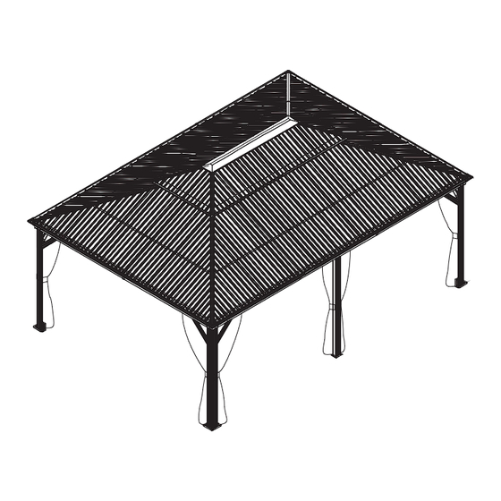
- Page 31 Overall roof assembly...
- Page 32 Put on mosquito sidewalls and solid sidewalls.
- Page 34 Thanks for your purchase. At domi outdoor living, we believe in our products. That’s why we provide a 12-month warranty and friendly, casy-to-reach after-sales service. So if you have any questions about our product and assembly- ,please feel free to contact us.
Need help?
Do you have a question about the LGMF1613 and is the answer not in the manual?
Questions and answers
Does the shipping boxes numbers relate to the parts list so I know what parts are in each box. The parts list doesn’t seem to reflect that? Thank you.
what type of screws are needed to secure the 4 posts to cement?