
Related Manuals for SystemAir fantech bathfan Select Fit SF Series


Summary of Contents for SystemAir fantech bathfan Select Fit SF Series
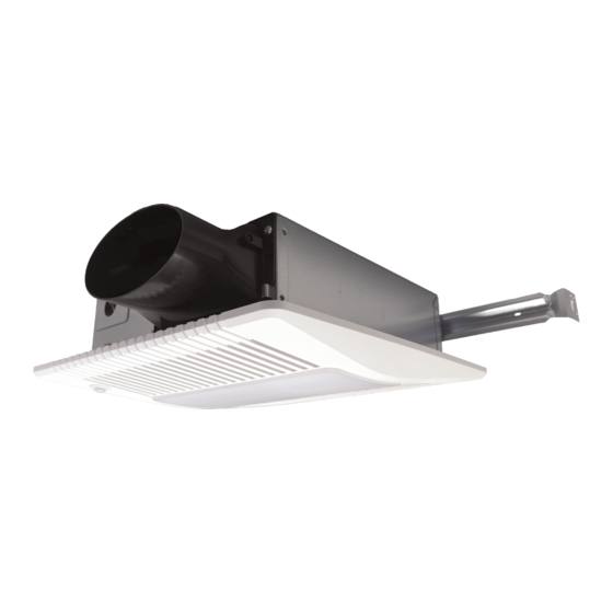
- Page 1 Installation, Operations, and Maintenance instruction bathfan Select Fit SF Series Ceiling Mount Exhaust Fan with Metal Casing...
-
Page 2: Table Of Contents
Table of contents 1 Introduction ............. 1 Product Description ........1 Intended Use..........1 Document Description ........1 Fantech Warranty........... 1 Product Overview ........... 1 Type Designation ........... 1 2 Safety ..............2 Safety definitions..........2 Safety Instructions.......... 2 Personal protective equipment ......2 3 Installation .............. -
Page 3: Introduction
Introduction Product Overview Product Description This product is a ceiling mount exhaust fan with a metal casing. This fan has rotating parts and personnel must exercise safety precautions during installation, operations, and maintenance. Intended Use Use this product only in the manner intended by Fantech. If you have any questions, please contact a Fantech representative. -
Page 4: Safety
• Never place a switch where it can be reached from a tub or Safety shower. • Do not use this product with any solid-state speed control Safety definitions device. Warnings, cautions and notes are used to point out specially •... -
Page 5: Installation
• Humidity above the set position (30–80% relative humidity) Installation • Fast changes in humidity To Set the Product Speed After 20 minutes, the product returns to the selected low airflow speed. Note: Legend for Diagram For only the bathfan Select Fit SF50-80-100 and the SF50- 80-100L products. -
Page 6: To Set The Product Speed
Note: SFC50–80–100H, SFC50–80–100HO, SFC50–80–100LH, & SFC50–80–100LHO The toggle switch will adjust the upper fan speed from 50, 80, or 100 Cubic Feet per Minute (CFM). CONTROL BOX H (%) To Set the Speed To adjust the preselected high airflow speed, change the control switches according to Figure 3. -
Page 7: To Mount With Mounting Holes
Before installation, remove the product from the packaging and set the packaging aside. Identify the locations of Hole A & Hole B, and the channels on the side of the product’s casing. B Screw A Screw Hanger Bar Hole B To Mount to One Side of the Hole A Framing... -
Page 8: To Plan The Duct Run
Floor Note: Cooking Equipment The minimum installation distance between studs is 13.375 Ceiling inches (340mm). Cooking Area Engage (1) hanger bar with the appropriate channel on the product’s casing. 3.10 To Attach the Duct Adjust hanger bar as necessary to mount the product be- tween the framing. -
Page 9: To Manage The Duct Run
3.11 To Manage the Duct Run Caution Using duct tape, attach additional ducts to the product to To avoid damage to exterior finishes and to make sure air is released to the outdoors. allow for easier parts replacement, make sure screws are installed from the inside. Depending on the shortest &... -
Page 10: Electrical Connection
Electrical connection Note: Before this product is mounted, make sure all personnel To do before the electrical knows that installing the radiation damper will increase the connection size of this product. Adjust how this product is installed as specified in the applicable procedure. •... - Page 11 Legend for Diagram SF50–80–100 BLACK (BLK) WHITE (WHT) English Terminology Meaning GROUND (GRD) ON/OFF SWITCH On/Off Switch WIRE UNIT PANEL LINE IN Line In SWITCH LIGHT SWITCH Light Switch RECEPTACLE SWITCH I Switch 1 — User Adjustable Airflow SWITCH BOX SWITCH II Switch 2 —...
-
Page 12: To Attach The Ceiling Grille
Note: SFC50–80–100, SFC50–80–100H, SFC50–80–100HO This product uses an occupancy sensor. It operates at the BLACK (BLK) WHITE (WHT) selected low airflow speed continuously and will automati- BROWN (BRN) GROUND (GRD) cally increase to the set high speed when the product de- tects motion. -
Page 13: Operation
Operation To Start the Product Note: To operate this product with automatic features (continuous flow, humidity sensing, and time delay features), and to oper- ate this product at the set user-adjusted airflow rate, observe the steps that follow: Set Switch I to the ON position and set Switch II to the OFF position. -
Page 14: Troubleshooting
This feature sets the speed of the product’s airflow to the low airflow speed and holds the low airflow speed continuously if switch I is set to the ON position, if switch II is set to the OFF position, if relative humidity is below the set level, and if the oc- cupancy sensor does not detect motion. -
Page 15: To Adjust The Humidity Sensor
Problem Cause Solution The Humidity Sensor Knob may need to The product operates too often when be adjusted. To adjust the Humidity Changing of seasons, temperature, or environmental conditions change. Sensor Knob, refer to the 6.1 To Adjust other conditions. the Humidity Sensor section. -
Page 16: Maintenance
Maintenance Technical data Technical Data Overview Warning Set the installed switch(es) in the OFF Voltage, Motor Power, Frequency Refer to the mo- position before you do the maintenance tor nameplate on unless the instructions tell you differently. the blower Make sure that the switch(es) is not assembly. - Page 17 bathfan Select Fit SF50- 80-100, #484305 bathfan Select Fit SF50- 80-100L, #484306 bathfan Select Fit SFC50- 80-100, #484307 bathfan Select Fit SFC50- 80-100H, #484308 10–1/4 (260) 4 (102) 10–1/4 (260) 3–3/8 (86) 13–3/4 (349) 13 (330) bathfan Select Fit SFC50- 80-100HO, #484309 bathfan Select Fit SFC50- 80-100L, #484310...
- Page 18 last page Canada Latin America (800) 747 1762 (800) 565 3548 +52 55 1328 7328 support@fantech.net support@fantech.net support@fantech.net © Copyright Fantech All rights reserved Fantech reserves the rights to alter their products without notice. This also applies to products already ordered, as long as it does not affect the previously agreed specifications.
Need help?
Do you have a question about the fantech bathfan Select Fit SF Series and is the answer not in the manual?
Questions and answers