
Related Manuals for SystemAir fantech bathfan Select S Series


Summary of Contents for SystemAir fantech bathfan Select S Series
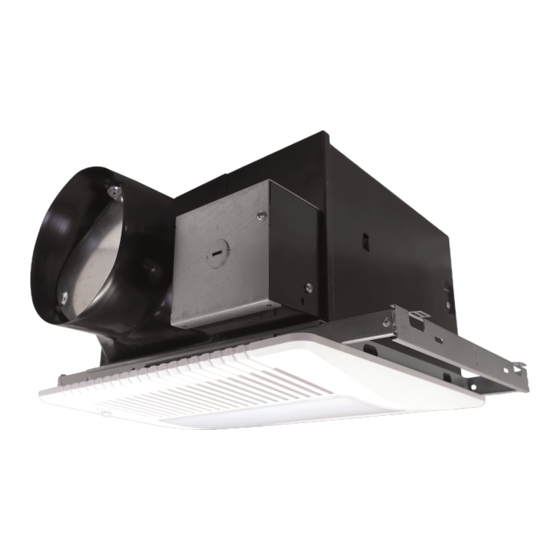
- Page 1 Installation, Operations, and Maintenance instruction bathfan Select S Series Ceiling Mount Exhaust Fan with Metal Casing...
-
Page 2: Table Of Contents
Table of contents 1 Introduction ............. 1 Product Description ........1 Intended Use..........1 Document Description ........1 Fantech Warranty........... 1 Product Overview ........... 1 Type Designation ........... 1 2 Safety ..............2 Safety definitions..........2 Safety Instructions.......... 2 Personal protective equipment ......2 3 Installation .............. -
Page 3: Introduction
Introduction Product Overview Product Description This product is a ceiling mount exhaust fan with a metal casing. This fan has rotating parts and personnel must exercise safety precautions during installation, operations, and maintenance. Intended Use Use this product only in the manner intended by Fantech. If you have any questions, please contact a Fantech representative. -
Page 4: Safety
• Never place a switch where it can be reached from a tub or Safety shower. • Do not use this product with any solid-state speed control Safety definitions device. Warnings, cautions and notes are used to point out specially •... -
Page 5: Installation
Installation SC50–80–110 & SC50–80–110L To Set the Product Speed Note: For only the bathfan Select SC50–80–110 and the SC50– 20min 40min 80–110L products. 5min Max. 60min Legend for Diagram SWITCH POSITION English Terminology Meaning AIRFLOW (CFM)* CONTROL BOX Control Box Low Airflow Knob To Set the Product Speed T (min) -
Page 6: To Set The Product Speed
To Set the Product Speed Note: The toggle switch will adjust the upper fan speed from 110, Note: 130, or 150 Cubic Feet per Minute (CFM). For only the bathfan Select SC110-130-150H, SC110-130- 150LH, and the SC110-130-150LHO products. To adjust the preselected high airflow speed, change the control switches according to Figure 3. -
Page 7: To Plan The Duct Run
To Plan the Duct Run Warning Do not install the product above or inside the area within 45 degrees on either side of any kind of cooking equipment. Refer to Figure 7. Screw Hole B Screw To Engage the Product Casing with the Duct Connector Casing Using (1) A screw, attach duct connector to the frame. -
Page 8: To Manage The Duct Run
Position the wires of the junction box through the strain relief. Once the wires of the junction box have been correctly connected, replace the junction box cover. Using duct tape, attach the duct to the duct connector. Examine the duct around the duct connector to make sure the seal is air tight. - Page 9 Align the (4) screw holes of the radiation damper with the Screw Hole (4) screw holes of the radiation damper casing. B Screws With the arrow on the nameplate in the “up” position, en- gage the radiation damper with the bottom of the radiation damper casing.
-
Page 10: Electrical Connection
Electrical connection Legend for Diagram To do before the electrical English Terminology Meaning connection ON/OFF SWITCH On/Off Switch • Make sure that the electrical connection agrees with the LINE IN Line In product specification on the motor name plate. LIGHT SWITCH Light Switch •... -
Page 11: To Attach The Ceiling Grille
S110-130-150 SC50–80–110 & SC110-130-150H BLACK (BLK) WHITE (WHT) BLACK (BLK) WHITE (WHT) GROUND (GRD) BROWN (BRN) GROUND (GRD) WIRE WIRE UNIT UNIT SWITCH I PANEL PANEL RECEPTACLE SWITCH RECEPTACLE SWITCH II SWITCH BOX SWITCH BOX POWER SUPPLY 120V AC POWER SUPPLY 120V AC SC50–80–110L, SC110-130-150LH, &... - Page 12 Note: This product uses an occupancy sensor. It operates at the selected low airflow speed continuously and will automati- cally increase to the set high speed when the product de- tects motion. After the set time, the product returns to the selected low speed airflow.
-
Page 13: Operation
This feature sets the speed of the product’s airflow to the low Operation airflow speed and holds the low airflow speed continuously if switch I is set to the ON position, if switch II is set to the OFF To Start the Product position, if relative humidity is below the set level, and if the oc- cupancy sensor does not detect motion. -
Page 14: Troubleshooting
Condition 2 – If the time delay knob is set in the OFF (OFF–5 minutes) position and if the humidity sensor knob is set be- tween 30–80%, the product will return to the low airflow speed in 5 minutes. Condition 3 – If the time delay knob is set between 5–60 mi- nutes and if the humidity sensor knob is set between 30–80%, the product will return to the low airflow speed in 5–60 minutes. -
Page 15: Maintenance
Maintenance Warning Set the installed switch(es) in the OFF position before you do the maintenance unless the instructions tell you differently. Make sure that the switch(es) is not accidentally set in the ON position. To Maintain the Product Caution Screw Hole Supplied Screws If the product suddenly starts to make loud noises, or starts to vibrate in an unusual... -
Page 16: Technical Data
Technical data Voltage, Motor Power, Frequency Refer to the mo- tor nameplate on Technical Data Overview the blower assembly. Motor data Refer to the mo- tor nameplate or the technical documentation from the motor manufacturer. Product Dimensions... - Page 17 Note: Dimensions are given in inches (mm). bathfan Select SC50-80-110, #484313 bathfan Select SC50-80-110L, #484314 bathfan Select S110-130-150, #484315 bathfan Select S110-130-150L, 11–3/8 (289) 10–1/2 (267) 7–5/8 (194) 6 (152) 13 (330) 13–3/4 (349) #484316 bathfan Select SC110-130- 150H, #484317 bathfan Select SC110-130- 150LH, #484318...
- Page 18 last page Canada Latin America (800) 747 1762 (800) 565 3548 +52 55 1328 7328 support@fantech.net support@fantech.net support@fantech.net © Copyright Fantech All rights reserved Fantech reserves the rights to alter their products without notice. This also applies to products already ordered, as long as it does not affect the previously agreed specifications.
Need help?
Do you have a question about the fantech bathfan Select S Series and is the answer not in the manual?
Questions and answers