Advertisement
Quick Links
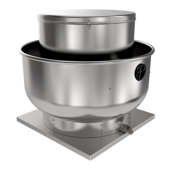
PRV Series
Power Roof Ventilators
Fantech, Inc. and Systemair
Mfg. certify that the ventila-
tors shown herein are licensed
to bear the AMCA Seal. The
ratings shown are based
on tests and procedures
performed in accordance with
AMCA Publication 211 and
AMCA Publication 311 and
comply with the requirements
of the AMCA Certified Ratings
Program.
Techical / Customer Support:
United States Tel.: 800.747.1762
Installation and Operational Manual
Canada Tel.: 800.565.3548
Item #: 481806
Rev Date: 2016-11-11
Advertisement

Related Manuals for SystemAir Fantech PRV Series


Summary of Contents for SystemAir Fantech PRV Series
- Page 1 Item #: 481806 Rev Date: 2016-11-11 Installation and Operational Manual PRV Series Power Roof Ventilators Fantech, Inc. and Systemair Mfg. certify that the ventila- tors shown herein are licensed to bear the AMCA Seal. The ratings shown are based on tests and procedures...
- Page 2 Note Warning / Information Technical Practical tip Important information note Always disconnect, lock, and tag power source before installing or 4. Motor and fan must be securely grounded (bare metal) to a suitable servicing. Failure to disconnect power source can result in fire, shock, or electric ground, such as a grounded water pipe or ground wire serious injury.
-
Page 3: Installation And Maintenance Information
INSTALLATION AND MAINTENANCE INFORMATION Receiving, Inspection & Unpacking Unpack each carton or crate and verify that all required parts and proper When the equipment is received all items should be carefully checked quantities of each item have been received. Refer to drawings for part against the bill of lading to be sure all crates and cartons have been descriptions. - Page 4 Roof Fan Installation 3. Bolt the fan base to the roof curb through the Downblast Fans (5BDD, 5DDD) Upblast Fans (5BDU, 5 DDU): holes provided on the base using eight (8) lag 1.Position the fan with its wiring conduit in line 1.
- Page 5 BEFORE START-UP: Disconnect power to this unit NOTE: The fan should not need belts over the edge of either sheave. A new before servicing the unit. balancing, as it was balanced at belt may be seriously damaged internally by 1. Check to verify that the wheel is free to the factory to be within stringent careless handling (see Figure 5).
- Page 6 a. Tighten all setscrews, bolts and wire 8. The belt alignment should also be checked to Figure 3. Alignment connections. be sure the belt is running perpendicularly b. Check belt tension and sheaves for wear. to the rotating shafts. Fan and motor shafts c.
-
Page 7: Fan Troubleshooting Chart
Intervals Type of service Maunfacturer Grease (NLGI #2) 12 to 8 Infrequent operation or light duty in clean atmosphere Shell Alvania RL2 6 to 12 8 to 16 hrs./day in clean, relatively dry atmosphere Exxon/Mobil Ronex MP 3 to 6 12 to 24 hrs./day, heavy duty, or if moisture is present Table 2. - Page 8 Dimensions Belt-Drive Downblast Roof Ventilators Model Wheel Shaft Size Dimensions Shipping Recommended Roof Curb Size Diameter Weight Opening 10 1 / 25 3 / 22 7 / 1 1 / 14 1 / 17 1 / 5BDD 10 12 1 / 23 3 / 1 1 / 17 1 /...
- Page 9 Dimensions (cont.) Belt-Drive Upblast Roof Ventilators Model Wheel Shaft Size Dimensions Shipping Recommended Roof Curb Size Diameter Weight Opening 10 1 / 23 7 / 25 3 / 16 7 / 1 1 / 14 1 / 17 1 / 5BDU 10 12 1 / 26 1 /...
-
Page 10: Wiring Diagrams
Wiring Diagrams 5BDU & 5BDD 10BB; 12BB; 12CB; 13BB; 13CB; 13DB; 15BB; 15CB; 15DB; 16CB; 16DB; 18CB; 18DB; 20CB; 20DB; 24CB; 24DB; 30DB; 5FSU 10BB & 10CB CAPACITOR START MOTOR LOW VOLT CONN. HIGH VOLT CONN. TAPE TAPE TAPE LINE LINE LINE LINE... - Page 11 Wiring Diagrams (cont.) 5BDU & 5BDD 15EB; 15FB; 15EB; 16FB; 18EB; 18FB; 18GB; 20EB; 20FB; 20GB; 24EB; 24FB; 24GB; 30EB; 30FB; 30GB; 36EB; 36FB; 36GB; 5FSU 10FB; 12EB; 15FB; 15GB & 18GB CONNECTIONS UNGROUNDED SIDE OF LINE 115 V 208-230 V LINE LINE LINE...
- Page 12 Wiring Diagrams (cont.) 5FSU 10DB VOLTS VOLTS PLASTIC POCKET TO REVERSE ROTATION INTERCHANGE RED & BLK LEADS Motor Location Diagram Incorrect motor location Correct motor location 1. Mount motor in matching slot pattern provided. 2. Install belt with motor bolts finger tight & slide motor to the right until belt is tight.
- Page 13 Shell Belt Drive Fan Components List 1 Phase 3 Phase Shell Roof curb Drive Pack Motor Drive Pack Motor Model Art. # Weight, Model Art. # Weight, Art. # DP ID Art. # Motor ID Art. # DP ID Item # Motor Opening Dimensions...
- Page 14 Shell Belt Drive Fan Components List (cont.) 1 Phase 3 Phase Shell Roof curb Drive Pack Motor Drive Pack Motor Model Art. # Weight, Model Art. # Weight, Art. # DP ID Art. # Motor ID Art. # DP ID Item # Motor Opening...
-
Page 15: Limitation Of Warranty And Liability
Warranty Fantech, Inc. warrants to the original purchaser that our products will be If within thirty (30) days after purchaser’s discovery of any warranty free from defects in material and workmanship for a period of one (1) defects within the warranty period, purchaser notifies us thereof in year from the date of shipment. - Page 16 Fantech reserves the right to make technical changes. For updated documentation please refer to www.fantech.net Fantech®...
Need help?
Do you have a question about the Fantech PRV Series and is the answer not in the manual?
Questions and answers