Table of Contents
Advertisement
Quick Links
Advertisement
Table of Contents

Subscribe to Our Youtube Channel
Related Manuals for METREL TeraOhmLT 10kV


Summary of Contents for METREL TeraOhmLT 10kV
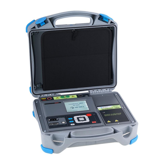
- Page 1 TeraOhmLT 10kV MI 3209 Instruction manual Version 1.1.1; Code No. 20 753 234...
- Page 2 Mark on your equipment certifies that it meets requirements of all subjected EU regulations Hereby, Metrel d.d. declares that the MI 3209 is in compliance with subjected EU directives. The full text of the EU declaration of conformity is available at the following internet address https://www.metrel.si/DoC.
-
Page 3: Table Of Contents
MI 3209 TeraOhmLT 10kV Table of contents Table of contents General Description .................... 5 Features ......................5 Safety and operational considerations ............. 6 Warnings and notes ..................6 Battery and charging of Lead – Acid battery ..........8 2.2.1 Precharge ....................9 Standards applied .................. - Page 4 MI 3209 TeraOhmLT 10kV Table of contents Voltage dependence test – Step Voltage Test ........30 5.2.2 Time dependence test – Diagnostic Test ..........31 5.2.3 5.2.4 Withstanding Voltage Test ..............32 Guard terminal .................... 33 Averaging options ..................34 5.4.1...
-
Page 5: General Description
1 General Description Features TeraOhmLT 10kV (MI 3209) is a portable battery or mains powered test instrument with excellent IP protection (IP65), intended for diagnosing of Insulation Resistance by using high test voltages of up to 10 kV. It is designed and produced with the extensive knowledge and experience acquired through many years of working in this field. -
Page 6: Safety And Operational Considerations
Warnings and notes In order to maintain the highest level of operator safety while carrying out various tests and measurements Metrel recommends keeping your TeraOhmLT 10kV test equipment in good condition and undamaged. When using this test equipment, consider the following general warnings: symbol on the test equipment means »Read the Instruction manual with... - Page 7 Note: For manual discharge Metrel recommends the use of A 1513 Discharge link. The ❑ internal discharge resistors of A 1513 ensure a damped discharge up to 10 uF at 10 kV.
-
Page 8: Battery And Charging Of Lead - Acid Battery
MI 3209 TeraOhmLT 10kV Safety and operational considerations Battery and charging of Lead – Acid battery The instrument is designed to be powered by rechargeable Lead – Acid battery or with mains supply. The LCD contains an indication of battery condition and the power source (upper left section of LCD). -
Page 9: Precharge
MI 3209 TeraOhmLT 10kV Safety and operational considerations Typical charging profile which is also used in this instrument is shown in Figure 2.4. Current Regulation LOWV CH/8 Precharge Fastcharge Safety Time Time Figure 2.4: Typical charging profile where: ....... Battery charging voltage ...... - Page 10 MI 3209 TeraOhmLT 10kV Safety and operational considerations Typical charging time is 4 hours in the temperature range of 5°C to 60°C. Charge Charge Charge Suspended Suspended ch/8 Temperature Figure 2.6: Typical charging current vs temperature profile where: ......... Cold temperature threshold (typ. -15°C) ......
-
Page 11: Standards Applied
MI 3209 TeraOhmLT 10kV Safety and operational considerations Standards applied The TeraOhmLT 10kV instrument is manufactured and tested in accordance with the following regulations: Electromagnetic compatibility (EMC) EN 61326 Electrical equipment for measurement, control and laboratory use – EMC requirements Class A... -
Page 12: Instrument Description
MI 3209 TeraOhmLT 10kV Instrument description 3 Instrument description Instrument casing The instrument is housed in a plastic box that maintains the protection class defined in the general specifications. Operator’s panel The operator’s panel is shown in Figure 3.1 below. - Page 13 MI 3209 TeraOhmLT 10kV Instrument description 12,13 GUARD Guard input terminals. - Rx Negative high voltage input terminal. Power and Communication Section: Input power supply socket (C7) USB communication port (standard USB connector - type B) RS232 communication port (standard RS232 9-pin D...
-
Page 14: Accessories
The standard length of high voltage shielded test leads with (red, black) banana connectors is 3 m; optional lengths are 8 m and 15 m. For more details see attached list for standard configuration and options or contact your distributor or see the METREL home page: http://www.metrel.si. - Page 15 MI 3209 TeraOhmLT 10kV Instrument description Test tips Application notes: Test tips applied on High voltage ❑ shielded test leads are designed for CAT IV 600 V TRMS voltage measurement. Figure 3.4: Test tips...
-
Page 16: Display Organization
MI 3209 TeraOhmLT 10kV Instrument description Display organization Figure 3.5: Typical function display and graph screen 1 Measurement result window 2 Measurement control window 3 Messages window 4 Battery, time and communication indication 5 Measurement result line 6 Graphical presentation of measured data 3.4.1 Measurement result window... -
Page 17: Measurement Control Window
MI 3209 TeraOhmLT 10kV Instrument description Bar graph Graphically represents measured insulation resistance in respect to the measurement range. It also displays limit value if it is enabled. Shows the output voltage. During measurement campaign this result is refreshed every few seconds. When the measurement is completed, result is hold on screen, until new measurement is started. -
Page 18: Message Window
MI 3209 TeraOhmLT 10kV Instrument description Allows user to set the desired test voltage. Timer1 Allows user to set the desired measurement duration in Insulation Resistance test. Delay for starting DAR measurement in Diagnostic test. (mm:ss) – step 1 s (max time 99 min). -
Page 19: Battery, Time And Communication Indication
MI 3209 TeraOhmLT 10kV Instrument description High voltage is present on measuring terminals (> 50 V rms). Test result can be saved. AC noise is present on the measuring terminals (+ Rx, - Rx). A Breakdown or Over voltage event has accrued. -
Page 20: Measurement Result Line
MI 3209 TeraOhmLT 10kV Instrument description 3.4.5 Measurement result line Shows Insulation resistance. During measurement campaign this result is refreshed every few seconds. When the measurement is completed, it represents Insulation resistance at cursor position. Shows the output voltage. During measurement campaign this result is refreshed every few seconds. -
Page 21: Main Menu
MI 3209 TeraOhmLT 10kV Main menu 4 Main menu Instrument Main menu From the Main menu of the instrument there are four options available: Measurements, Memory menu, Settings menu and Help menu. Figure 4.1: Instrument Main menu Keys: Select one of the following menu items: <Measurements>... -
Page 22: Memory Menu
MI 3209 TeraOhmLT 10kV Main menu Memory menu Measurement result with all relevant parameters can be stored into the instrument’s memory. The instrument’s memory space is divided into 3 levels: OBJECT, DUT and LINE. The OBJECT, DUT and LINE level can contain up to 199 locations. -
Page 23: Recalling Results
MI 3209 TeraOhmLT 10kV Main menu 4.2.2 Recalling results To enter Recall results menu in Memory menu SELECT key should be pressed. Figure 4.4: Recall Results menu Figure 4.5: Recalled result screen Keys in Recall menu: Selects one of the following items OBJECT / DUT / LINE. -
Page 24: Deleting Results
MI 3209 TeraOhmLT 10kV Main menu 4.2.3 Deleting results To enter Delete results menu in Memory menu SELECT key should be pressed. Single measurement or all measurements under selected OBJECT, DUT and LINE can be deleted. Figure 4.6: Delete all measurements under selected Object Keys in Delete results menu: ... -
Page 25: Settings Menu
MI 3209 TeraOhmLT 10kV Main menu Settings menu In the Settings menu different parameters and settings of the instrument can be viewed or set. Figure 4.7: Settings menu Keys: Select the setting to adjust or view: <Language> instrument language; <Initial Settings> factory settings;... -
Page 26: Language Selection
MI 3209 TeraOhmLT 10kV Main menu 4.3.1 Language selection The instrument language can be set. Keys: ➢ Toggles between different languages (changes are stored automatically). Note: No confirmation is needed to set the desired language. ❑ 4.3.2 Initial Settings selection In this menu the following instrument parameters can be set to their initial values: All measurement parameters;... -
Page 27: Transfer Mode
MI 3209 TeraOhmLT 10kV Main menu 4.3.5 Transfer mode The instrument communication mode can be set. Keys: ➢ Toggles between RS232 and USB. Note: No confirmation is needed to set the desired transfer mode. ❑ 4.3.6 Contrast selection In this selection the contrast of the display can be set. -
Page 28: Break Down Selection
MI 3209 TeraOhmLT 10kV Main menu 4.3.9 Break Down selection In this selection the Break down can be set. When triggered the Break down circuit automatically stops the measuring procedure. Keys: ➢ Toggles between YES or NO (changes are stored automatically). -
Page 29: Measurements
MI 3209 TeraOhmLT 10kV Measurements 5 Measurements General information about high voltage testing 5.1.1 The purpose of insulation tests Insulating materials are important parts of almost every electrical product. The material’s properties depend not only on its compound characteristics but also on temperature, pollution, moisture, ageing, electrical and mechanical stress, etc. -
Page 30: Some Application Examples
MI 3209 TeraOhmLT 10kV Measurements Figure 5.1: Insulating material where: and R ....Surface resistivity (position of optional guard connection) iss1 iss2 ......... Actual insulation resistance of material ......... Capacitance of material ......Represents polarization effects ........Overall test current (I... -
Page 31: Time Dependence Test - Diagnostic Test
In general, insulators that are in good condition will show a “high” polarization index while insulators that are damaged will not. Note that this rule is not always valid. Refer to Metrel’s handbook Insulation Testing Techniques for more information. General applicable values:... -
Page 32: Withstanding Voltage Test
MI 3209 TeraOhmLT 10kV Measurements 5.2.4 Withstanding Voltage Test Some standards allow the use of a DC voltage as an alternative to AC withstanding voltage testing. For this purpose, the test voltage has to be present across the insulation under test for a specific time. The insulation material only passes if there is no breakdown or flash over. -
Page 33: Guard Terminal
MI 3209 TeraOhmLT 10kV Measurements Guard terminal The purpose of the GUARD terminal is to lead away potential leakage currents (e.g. surface currents), which are not a result of the measured insulation material itself but are a result of the surface contamination and moisture. This current interferes with the measurement i.e. -
Page 34: Averaging Options
MI 3209 TeraOhmLT 10kV Measurements Averaging options Filters and additional averaging are built in to reduce the influence of noise on measurement results. This option enables more stable results especially when dealing with high Insulation Resistances. In Insulation Measurement the status of the averaging option is shown in measurement control window of the LCD screen. -
Page 35: Example Of Averaging
MI 3209 TeraOhmLT 10kV Measurements 5.4.2 Example of averaging Capacitive test object 200 nF Insulation Resistance Measurement Test parameters: Un = 5.00 kV Timer1 = 5:00 min Figure 5.3: Insulation Meas. (AVG _ _ _ ) Figure 5.4: Insulation Meas. (AVG 5s ) Figure 5.5: Insulation Meas. -
Page 36: Measurement Menu
MI 3209 TeraOhmLT 10kV Measurements Measurement menu In the Measurement menu 5 different measurements and tests can be selected. Figure 5.7: Measurement menu Keys: Selects measurement or test. SELECT Enters selected measurement function window. Returns to the Main menu. -
Page 37: Insulation Resistance Measurement
MI 3209 TeraOhmLT 10kV Measurements Insulation Resistance Measurement Test can be started from the Insulation Resistance Measurement window. Before carrying out a test the parameters output voltage, timer, high limit and additional averaging can be edited. Figure 5.8: Insulation Resistance Measurement menu Test parameters for Insulation resistance Measurement Set test voltage –... - Page 38 MI 3209 TeraOhmLT 10kV Measurements Insulation Measurement procedure: Select the Insulation Resistance Measurement function. ❑ Set the test parameters (voltage, timer, high limit, averaging). ❑ Connect the test leads to the instrument and to the test object. ❑ Press the START/STOP key to start the measurement.
-
Page 39: Set Limit
MI 3209 TeraOhmLT 10kV Measurements 5.6.1 Set Limit With the high limit the user is allowed to set the limit resistance value. Measured resistance is compared against the limit. Result is validated only if it is within the given limit. Limit indication is shown by the bar Bar –... -
Page 40: Diagnostic Test
MI 3209 TeraOhmLT 10kV Measurements Diagnostic test Diagnostic test is a long duration test for evaluating the quality of the insulation material under test. The results of this test enable the decision to be made on the preventive replacement of the insulation material. Test can be started from the Diagnostic Test window. - Page 41 MI 3209 TeraOhmLT 10kV Measurements Diagnostic Test procedure: Select the Diagnostic test function. ❑ Set the test parameters (voltage, timer1 …). ❑ Connect the test leads to the instrument and to the test object. ❑ Press the START/STOP key to start the measurement.
-
Page 42: Dielectric Absorption Ratio (Dar)
MI 3209 TeraOhmLT 10kV Measurements 5.7.1 Dielectric Absorption Ratio (DAR) DAR is ratio of Insulation Resistance values measured after 30 s and after 1 minute. The DC test voltage is present during the whole period of the test (also an Insulation Resistance measurement is continually running). -
Page 43: Dielectric Discharge Testing (Dd)
MI 3209 TeraOhmLT 10kV Measurements Note: When determining Riso (1 min) pay close attention to the capacitance of the test ❑ objects. It has to be charged-up in the first time section (1 min). Approximate maximum capacitance using: where: t ........period of first time unit (e.g. 1 min). - Page 44 MI 3209 TeraOhmLT 10kV Measurements t [s] Figure 5.16: The current/time diagram of a good and bad insulation tested with dielectric discharge method The dielectric discharge test is very useful for testing a multi-layer insulation. This test can identify excess discharge currents that occur when one layer of a multi-layer insulation is damaged or contaminated.
-
Page 45: Step Voltage Testing
MI 3209 TeraOhmLT 10kV Measurements Step Voltage testing In this test, the insulation is measured in five equal time periods with test voltages from one fifth of the final test voltage up to full scale (Figure 5.17). This function illustrates the relationship of a materials Insulation resistance and its applied voltage. - Page 46 MI 3209 TeraOhmLT 10kV Measurements Figure 5.18: Example of Step Voltage test Figure 5.19: Example of Step Voltage result test graph view 0.8Un 0.6Un 0.4Un 0.2Un 0.2T 0.4Ts 0.6Ts 0.8Ts Figure 5.20 Step-up voltage test Warnings: Refer to Warnings chapter for safety precautions! ❑...
-
Page 47: Withstanding Voltage Test
MI 3209 TeraOhmLT 10kV Measurements Withstanding Voltage Test This function offers Withstanding Voltage Test of insulation material. It covers two types of tests: Breakdown voltage testing of high voltage device, e.g. transient suppressors. ❑ DC withstanding voltage test for insulation coordination purposes. - Page 48 MI 3209 TeraOhmLT 10kV Measurements Figure 5.22: Example of Withstanding Voltage test result START START RAMP Figure 5.23 Test voltage presentation without breakdown ......Starting test voltage. START ....... End test voltage......Duration of test ramp. RAMP ......Duration of starting test voltage.
-
Page 49: True Rms Voltmeter
MI 3209 TeraOhmLT 10kV Measurements True RMS Voltmeter It is a simple function that continuously measures the voltage and frequency across +Rx and -Rx connectors. Measured voltage and frequency in function True RMS Voltmeter can be stored. This function is intended for quick verification of possible presence of voltage on tested object. -
Page 50: Communication
MI 3209 TeraOhmLT 10kV Communication 6 Communication The instrument can communicate with the HVLink PRO PC software. The following action is supported: ➢ Saved results can be downloaded and stored to a PC. A special communication program on the PC automatically identifies the instrument and enables data transfer between the instrument and the PC. -
Page 51: Maintenance
MI 3209 TeraOhmLT 10kV Maintenance 7 Maintenance Unauthorized persons are not allowed to open the TeraOhmLT 10kV instrument. There are no user replaceable components inside the instrument, except the battery. Batteries insertion and replacement Battery is stored in the battery compartment of the instrument casing under the battery cover (see Figure 7.1). - Page 52 MI 3209 TeraOhmLT 10kV Maintenance Figure 7.2: Correctly inserted battery Step 5 Fix the battery cover back in place. Ensure batteries are used and disposed of in accordance with Manufacturer’s guidelines and in accordance with Local and National Authority guidelines.
-
Page 53: Cleaning
MI 3209 TeraOhmLT 10kV Maintenance Cleaning No special maintenance is required for the housing. To clean the surface of the instrument, use a soft cloth slightly moistened with soapy water or alcohol. Then leave the instrument to dry totally before use. -
Page 54: Technical Specifications
MI 3209 TeraOhmLT 10kV Technical specifications 8 Technical specifications Nominal test voltage range ......50 V – 10 kV Voltage step ..........50 V (50 V – 1 kV) and 100 V (1 kV – 10 kV) Voltage output accuracy ......-0%, +10% 10 V Current capability of test generator .... - Page 55 MI 3209 TeraOhmLT 10kV Technical specifications Current Measuring range (A) Resolution (A) Accuracy 10 1.00 ... 5.00 m 100 ... 999 1 10.0 ... 99.9 100 n (5 % of reading + 3 digits) 1.00 ... 9.99 ...
-
Page 56: True Rms Voltmeter
MI 3209 TeraOhmLT 10kV Technical specifications Dielectric discharge test DD Display range DD Resolution Accuracy 0.01 ... 9.99 0.01 (5 % of reading + 2 digits) 10.0 ... 100.0 Table 8.7: DD display ranges and accuracy Notes: All data regarding accuracy is given for nominal (reference) environment condition ❑... -
Page 57: General Data
MI 3209 TeraOhmLT 10kV Technical specifications General data Battery power supply ......12 V DC (3.4 Ah Lead – Acid) Battery charging time ......typical 4 h (deep discharge) Max. battery charging environmental temperature ....40 °C Battery operation time: Idle state ...........
Need help?
Do you have a question about the TeraOhmLT 10kV and is the answer not in the manual?
Questions and answers