Table of Contents
Advertisement
Thermostat 508 and 509
Table of Contents
Display / Keypad Operation ............ pg 1
Display Symbols ............................. pg 2
General ........................................ pg 2-3
Sequence of Operation................pg 3-4
Installation - Slab Sensor 079 ......pg 4-6
Installation - Thermostats ............ pg 7-8
Wiring Examples ........................ pg 9-10
User Interface ................................pg 11
This brochure is for Thermostats 508 and 509 (with sensor). The section on the 079 slab
sensor installation is for the 509 only!
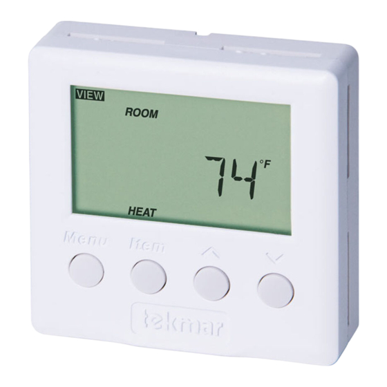
Display / Keypad Operation
The thermostat's display has four distinct fields. These fields are the Menu field, the Item
field, the Number field and the Status field. The four buttons on the face of the thermostat are
used to navigate through the menus and items to view and / or adjust the desired settings.
Displays the
current
menu
Displays the current
status of the
thermostat's inputs,
outputs and operation
- Data Brochure
1 of 16
Menus .......................................pg 12-14
View Menu .............................. pg 12
Adjust Menu .......................... pg 13
Schedule Menu ...................... pg 14
Error Messages ........................... pg 14
Technical Data .............................. pg 15
Warranty ....................................... pg 16
Displays an abbreviated
name of the selected item
AWAY
Selects Menus, Items
and adjusts settings
© 2012
D 508
04/12
Replaces: 05/10
Displays the current value
of the selected item
D 508 - 04/12
Advertisement
Table of Contents

Related Manuals for Tekmar 509


Summary of Contents for Tekmar 509
-
Page 1: Table Of Contents
Wiring Examples ......pg 9-10 Warranty ........pg 16 User Interface ........pg 11 This brochure is for Thermostats 508 and 509 (with sensor). The section on the 079 slab sensor installation is for the 509 only! Display / Keypad Operation The thermostat’s display has four distinct fields. -
Page 2: Display Symbols
Display Symbols Warning Heat One Displays when an error exists. Displays when the heat contact is on. Access Level Displays when in the user access level. General CYCLES PER HOUR The thermostat operation is based on cycles per hour. The number of cycles per hour is adjustable through the HEAT CYC setting in the Adjust menu. -
Page 3: Sequence Of Operation
Outdoor Sensor An outdoor sensor can be connected to the thermostat. The temperature measured by an outdoor sensor does not affect the ON time of the relay and is only used for display purposes. ACCESS LEVELS The 508 thermostat has two access levels. These access levels restrict the number of items available in the menus of the thermostat. -
Page 4: Installation - Slab Sensor 079
Type 508 Includes: • • One Thermostat 508 • Data Brochure D 508 • • User Brochure U 508 Type 509 Includes: • • One Thermostat 508 • One 079 Slab Sensor • • Data Brochure D 508 User Brochure U 508... - Page 5 Thick Floor Coverings (greater than 3/8” (10 mm)) If a thick floor covering is to be installed directly to the subfloor, a groove 1/8” (4 mm) wide by 1/16” (2 mm) deep can be cut into the back of the flooring material to accommodate the wire for the sensor.
- Page 6 Sensor Testing Instructions © 2012 D 508 - 04/12 6 of 16...
-
Page 7: Installation - Thermostats
Installation - Thermostat STEP ONE REMOVING THE FRONT COVER Place a screwdriver or similar object into the small slot located in the top of the thermostat. Push the screwdriver against the plastic tab and pull the top of the front cover so that it pivots around the bottom edge of the base. - Page 8 STEP FOUR WIRING THE THERMOSTAT (Refer to the examples on the following page.) 24 V (ac) Power Connect the 24 V (ac) power to the R and C terminals of the thermostat. This connection provides power to the microprocessor and display of the thermostat. Auxiliary Sensor Either an indoor, slab, or outdoor sensor may be connected to the auxiliary sensor input.
-
Page 9: Wiring Examples
Wiring Examples Wiring to a tekmar Wiring Center 315 or 316 115 V (ac) 24 V (ac) Sensor Wires 944-02 Thermostat 508 One Stage Heat Power: 24 V ±10% 50/60 Hz 1.5 VA. Relay: 24 V (ac) 2 A Class 2... - Page 10 Wiring to Unpowered 24 V (ac) Relay 115 V (ac) 24 V (ac) Sensor Wires Unpowered 944-02 Thermostat 508 Relay One Stage Heat Power: 24 V ±10% 50/60 Hz 1.5 VA. Relay: 24 V (ac) 2 A Class 2 For 3 wires, Made in install jumper Canada...
-
Page 11: User Interface
User Interface MENU BUTTON The menus display in the Menu Field at the left of the LCD. Three menus are available: • View • Adjust • Schd (Schedule) To select a menu, press and release the Menu button. ITEM BUTTON In each menu, a group of items can be selected. -
Page 12: Menus
View Menu ROOM TARGET The current desired air temperature for the space. This item is only available in the Installer access level.(Must have an active air sensor.) ROOM The current air temperature for the space. (Must have at least one active air sensor. -
Page 13: Adjust Menu
Adjust Menu MODE Current mode of operation of the thermostat. OFF, HEAT ROOM HEAT Desired temperature for heating. (Must have an active air sensor and be set to HEAT.) 35 to 100°F (1.5 to 38.0°C) SLAB MINIMUM Minimum slab temperature. (Must have an active slab sensor.) OFF, 34 to 122°F (OFF, 1.0 to 50.0°C) SLAB MAXIMUM Maximum slab temperature. -
Page 14: Schedule Menu
Schedule Menu AWAY OVERRIDE Selects an automatic setback temperature of 62°F (16.5°C) without altering the normal room temperature setting (Slab minimum is ignored). Select between None & Away. Error Messages The thermostat was unable to read a piece of information stored in its memory. -
Page 15: Technical Data
Sensors NTC thermistor, 10 kΩ @ 77°F (25°C ±0.2°C) ß=3892 –Included 508 (None) 509 (079) –Optional tekmar type #: 070, 072, 073, 076, 077, 079, 084 Warranty Limited 3 Year (See D508 for full warranty) Slab Sensor 079 Literature D079, C079 Packaged weight 0.1 lb. -
Page 16: Warranty
Prod- uct was not installed in compliance with tekmar’s instructions and / or the local codes and ordinances; or if due to defective installation of the Product; or if the Product was not used in compliance with tekmar’s instructions.
Need help?
Do you have a question about the 509 and is the answer not in the manual?
Questions and answers