Tekmar 510 Data Brochure
Programmable thermostat
Hide thumbs
Also See for 510:
- User brochure (12 pages) ,
- Data brochure (12 pages) ,
- User brochure (12 pages)
Table of Contents
Advertisement
Programmable Thermostat 510 and 511
Table of Contents
Display / Keypad Operation ............ pg 1
Display Symbols ............................. pg 2
General ........................................ pg 2-3
Sequence of Operation................... pg 4
Installation - Slab Sensor 079 ...... pg 5-7
Installation - Thermostats ............pg 8-9
Wiring Examples ........................ pg 9-10
This brochure is for Thermostats 510 and 511 (with sensor). The section on the 079 slab
sensor installation is for the 511 only!
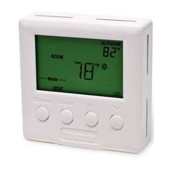
Display / Keypad Operation
The thermostat's display has four distinct fields. These fields are the Menu field, the Item
field, the Number field and the Status field. The four buttons on the face of the thermostat are
used to navigate through the menus and items to view and / or adjust the desired settings.
Displays the
current
menu
Displays the current
status of the
thermostat's inputs,
outputs and operation
- Data Brochure
1 of 16
Menus ....................................... pg 11-13
View Menu ...............................pg 11
Adjust Menu ...................... pg 11-13
Error Messages ..................... pg 14
Technical Data .............................. pg 15
Warranty ....................................... pg 16
Displays an abbreviated
name of the selected item
Selects Menus, Items
and adjusts settings
© 2012
D 510
02/12
Replaces: 09/09
Displays the current value
of the selected item
D 510 - 02/12
Advertisement
Table of Contents

Related Manuals for Tekmar 510


Summary of Contents for Tekmar 510
-
Page 1: Table Of Contents
Installation - Thermostats ....pg 8-9 Warranty ........pg 16 Wiring Examples ......pg 9-10 This brochure is for Thermostats 510 and 511 (with sensor). The section on the 079 slab sensor installation is for the 511 only! Display / Keypad Operation The thermostat’s display has four distinct fields. -
Page 2: Display Symbols
These sensors can be either indoor sensors, slab sensors, a remote sensor, or an outdoor sensor. © 2012 D 510 - 02/12 2 of 16... - Page 3 ACCESS LEVELS The tekmar Programmable Thermostat has two access levels. These access levels restrict the number of items available in the menus of the thermostat.
-
Page 4: Sequence Of Operation
Check the contents of this package. If any of the contents are missing or damaged, please contact your wholesaler or tekmar sales representative for assistance. Type 510 Includes: • • One Programmable Thermostat 510 • • Data Brochure D 510 • • User Brochure U 510 Type 511 Includes: •... -
Page 5: Installation - Slab Sensor 079
Slab Sensor 079 The tekmar Slab Sensor 079 has a stainless steel sleeve which is designed for use in concrete, thin-set or grout. The 079 is supplied with 10’ (3 m) of 2 conductor zipcord. Installation - Slab Sensor 079... - Page 6 AWG or larger wire can be spliced onto the two wires from the sensor. The splices should be properly soldered and protected in an accessible junction box. Follow the sensor testing instructions given in this brochure and then connect the wires to the control. © 2012 D 510 - 02/12 6 of 16...
- Page 7 Sensor Testing Instructions 7 of 16 © 2012 D 510 - 02/12...
-
Page 8: Installation - Thermostats
• Run wires from the 24 V (ac) power to the thermostat. Use a clean power source to ensure proper operation. • Run wires from the heating device to the thermostat. © 2012 D 510 - 02/12 8 of 16... -
Page 9: Wiring Examples
Align hinges on bottom of front cover Wiring Examples WIRING 24 V (AC) POWER AND AUXILIARY SENSORS 120 V (ac) 24 V (ac) Sensor Wires Auxiliary Sensor (Optional) 9 of 16 © 2012 D 510 - 02/12... - Page 10 Relay Zone Pump No Power 24 V (ac) Class 2 Transformer Wiring to Powered 24 V (ac) Relay Typical Powered Relay No Power Zone Pump 24 V (ac) Class 2 Transformer © 2012 D 510 - 02/12 10 of 16...
-
Page 11: Menus
(Must have an active air sensor and be set to Heat.) 35 to 100°F (1.5 to 38.0°C) SLAB MINIMUM (No Schedule) Minimum slab temperature. (Must have an active slab sensor.) OFF, 34 to 122°F (OFF, 1.0 to 50.0°C) 11 of 16 © 2012 D 510 - 02/12... -
Page 12: Adjust Menu
OFF, 34 to 122°F (OFF, 1.0 to 50.0°C) SLAB MAXIMUM Maximum slab temperature. This item is only available in the Installer access level. (Must have an active slab sensor.) 34 to 122°F, OFF (1.0 to 50.0°C, OFF) © 2012 D 510 - 02/12 12 of 16... - Page 13 Installer access level. OFF, ON LITE Sets the operation of the backlighting of the LCD. ON, Tmpy ON, OFF UNITS The units of temperature used to display the items. °F, °C 13 of 16 © 2012 D 510 - 02/12...
-
Page 14: Error Messages
The auxiliary sensor connected to the Sens 2 terminal is open circuit. Locate and repair the problem as described in the appropriate sensor brochure. After the fault is corrected, press any button to clear the error message. © 2012 D 510 - 02/12 14 of 16... -
Page 15: Programmable Thermostat 510 And
Sensors NTC thermistor, 10 kΩ @ 77°F (25°C ±0.2°C) ß=3892 –Included 510 (None), 511 (079) –Optional tekmar type #: 070, 072, 073, 076, 077, 079, 083, 084 Warranty Limited 3 Year (See D510 for full warranty) Slab Sensor 079 Literature D079, C079 0.1 lb. -
Page 16: Warranty
Prod- uct was not installed in compliance with tekmar’s instructions and / or the local codes and ordinances; or if due to defective installation of the Product; or if the Product was not used in compliance with tekmar’s instructions.
Need help?
Do you have a question about the 510 and is the answer not in the manual?
Questions and answers