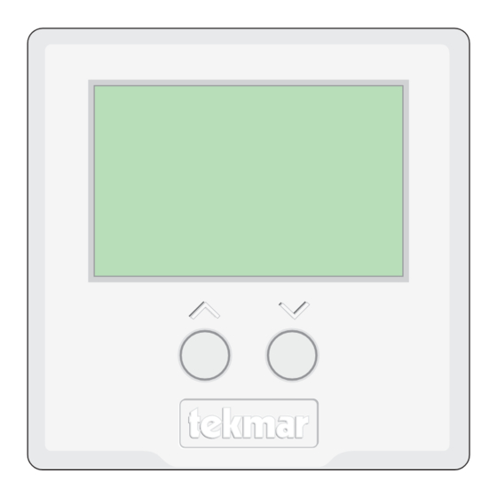
Tekmar 537 Mounting Instructions
Hide thumbs
Also See for 537:
- Installation & operation manual (20 pages) ,
- Quick setup manual (13 pages)
Table of Contents
Advertisement
Quick Links
- Wiring Brochure
tekmarNet
4 Thermostat 537
®
1
2
Information
Application
Brochure
Choose controls
Design your
to match
mechanical
application
applications
Overview
The following brochure describes how to wire the tekmarNet
stage of heat.
Table of Contents:
Definitions .......................................................................2
Rough-In Wiring .............................................................2
Remove the Wiring Cover ..............................................3
Mounting the Thermostat ...............................................3
Wiring Symbols ...............................................................3
3
Layout
Brochure
Brochure
Rough-in
wiring
instructions
4
Wiring
Brochure
Wiring and
installation of
specific control
4 (tN4) thermostat 537. The 537 has an output for one
®
tN4
Network
24 V (ac)
Power
Heating
Electrical Drawings .....................................................3, 4
Wiring the Thermostat ....................................................5
Troubleshooting the Wiring .............................................6
Testing the Wiring ...........................................................6
Technical Data ................................................................8
1 of 8
5
6
Data
Brochure
Control settings
Record settings &
and sequence of
wiring details for
operation
future reference
1
2
3
4
DIP
Switch
Settings
© 2009
W 537
01/09
Job
Record
W 537 - 01/09
Advertisement
Table of Contents

Summary of Contents for Tekmar 537
- Page 1 Overview The following brochure describes how to wire the tekmarNet 4 (tN4) thermostat 537. The 537 has an output for one ® stage of heat. Network 24 V (ac) Power Switch Settings...
- Page 2 Note: When multiple wires run to the same equipment location, wiring conductors can share one wire jacket. 1st Stage Heat 4 Cond. / 18 AWG 24 V (ac) Power Zone Manager tN4 Network © 2009 W 537 - 01/09 2 of 8...
- Page 3 The electrical drawing examples on the following pages show of the particular system being designed including additional the 537 in common applications. Choose the drawing that equipment isolation relays (for loads greater than the controls specified output ratings) and any safety devices most accurately depicts the components in your system and use that drawing as a guide to aid in wiring your system.
- Page 4 Electrical Application 537 E1 Description: 537 operates a hydronic heating system zone. Reset Zone Menu Item Module Manager Test Heating System 537 tNt Zone Manager © 2009 W 537 - 01/09 4 of 8...
- Page 5 • Connect W on the thermostat to W on the proper zone of the Zone Manager. If a Zone Manager is not used: Zone Manager • Connect W on the thermostat to the heating equipment Thermostat (such as a furnace). 5 of 8 © 2009 W 537 - 01/09...
- Page 6 24 V (ac) +/– 10%. Testing the Relays 1. Remove the front cover from the thermostat. 537 LCD Display Segments 2. Lower the Set Room temperature. The “H1” symbol should not be on the display. 3. Set electrical test meter to continuity.
- Page 7 Notes 7 of 8 © 2009 W 537 - 01/09...
- Page 8 Web Site: www.tekmarcontrols.com Product design, software and literature are Copyright © 2009 by: All specifications are subject to change without notice. 8 of 8 tekmar Control Systems Ltd. and tekmar Control Systems, Inc. Printed in Canada. W 537 - 01/09.


Need help?
Do you have a question about the 537 and is the answer not in the manual?
Questions and answers