
Related Manuals for RKI Instruments Eagle Series


Summary of Contents for RKI Instruments Eagle Series
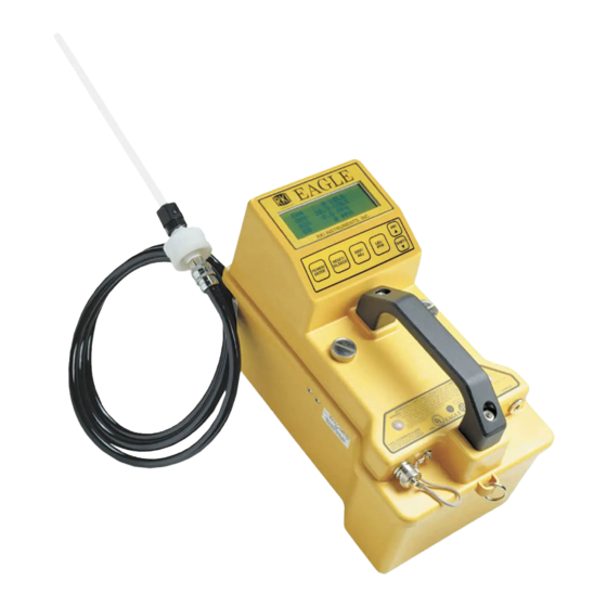
- Page 1 Instruction Manual Eagle Series Portable Multi-Gas Detector Part Number: 71-0028RK Revision: E Released: 9/19/11 www.rkiinstruments.com...
- Page 2 WARNING Read and understand this instruction manual before operating instrument. Improper use of the gas monitor could result in bodily harm or death. Periodic calibration and maintenance of the gas monitor is essential for proper operation and correct readings. Please calibrate and maintain this instrument regularly! Frequency of calibration depends upon the type of use you have and the sensor types.
-
Page 3: Warranty
Warranty RKI Instruments, Inc. warranties gas alarm equipment manufactured by RKI and sold by RKI to be free from defects in materials and workmanship for a period of one year from date of shipment from RKI Instruments, Inc. Any parts found defective within that period will be repaired or replaced, at our option, free of charge. -
Page 4: Table Of Contents
Table of Contents Introduction ..........1 Overview . - Page 5 Display Mode ......... . 19 User and Station ID Screen .
- Page 6 Calibration ..........41 Calibration Supplies and Equipment .
- Page 7 Appendix E: Infrared Methane Sensors ....66 Target Gases ..........66 Specifications .
-
Page 8: Introduction
Introduction Overview The RKI Eagle is the most advanced portable gas detection system available. The Eagle is built for rugged reliability and ease of use and includes the latest innovations in gas detection technology: • Simultaneous detection of one to six gases. Standard target gases include combustible gas (% LEL and ppm), oxygen deficiency, carbon monoxide, and hydrogen sulfide. -
Page 9: About This Manual
About this Manual This manual is intended for use with all Eagle models. Examples used in this manual are for the standard four-gas model (combustible gas, oxygen, carbon monoxide, and hydrogen sulfide). Differences between the standard four-gas model and other Eagle models are noted where applicable. -
Page 10: Specifications
Specifications Table 1 lists physical and environmental specifications for the Eagle. Table 2 lists specifications for the Eagle’s standard sensors. Target Gases Case Safety/Regulatory Dimensions Weight Power Continuous Operating Hours Operating Temperature Humidity Standard Accessories Optional Accessories 1 Appendices C, D, and E describe the Eagle’s non-standard sensors. 2 Consult RKI Instruments, Inc. - Page 11 Table 2 lists specifications for the Eagle’s standard sensors. Your Eagle model may not include all of the sensors listed below. The alarm settings are user-adjustable (see “Updating the Alarm Point Settings” on page 32.) Table 2: Standard Sensor Specifications Combustible Gas (%LEL Range...
-
Page 12: Description
Description Case The Eagle has a plastic case with a full-sized handle. The high- visibility case is shielded to reduce radio frequency and electromagnetic interference (RFI/EMI). The system is light-weight and balanced, which makes the Eagle easy to carry and use for extended periods. -
Page 13: Alarm Lights
Alarm Lights Two ultra-bright, red, light-emitting diodes (LEDs) provide visual alarms for gas concentrations and malfunctions. They are mounted on the top rear of the case for greatest visibility. Battery Charger Connector The battery charger connector is mounted on the top right rear of the case. -
Page 14: Sensors
Sensors This section describes the Eagle’s standard sensors. Non-standard sensors are described in Appendices C, D, and E. Your specific Eagle model may not include all of the sensors described below. Under normal conditions, the Eagle’s standard sensors have an operating life of approximately two years. -
Page 15: Circuit Boards
Circuit Boards The Eagle circuit boards analyze, record, control, store, and display the information collected. The analog PCB is mounted perpendicular to the base of the instrument case. It is located in the same half of the case as the sensors and sample-drawing system. -
Page 16: Operation
Operation The Eagle has four operating modes: normal operating mode, display mode, setup mode, and calibration mode. This section describes the Eagle in normal operating mode. It includes procedures to start up the Eagle, set various detection options for the combustible gas channel, and shut down the Eagle. - Page 17 The Battery Voltage screen displays the minimum usable and actual battery voltage (for example, 6.0V). If the battery voltage is too low, the Eagle will not continue. NOTE: The following screen only displays if the data logging option is installed. If the data logging option is not installed, the Self Diagnosis screen displays after the Battery Voltage screen.
-
Page 18: Normal Operation
4. Verify that the Eagle is operating correctly. Use the RKI Check Kit to easily verify correct operation of the Eagle. WARNING: If the Eagle does not respond to verification, take it to a known “fresh-air” environment, then perform the demand zero procedure described in “Preparing for Calibration”... - Page 19 set to CH4) calibrated to methane. Multiply the display reading by the factor in the appropriate column in the table. For example, if you are detecting hexane and the display reads 10% LEL, the actual hexane reading is 10% x 2.14 = 21% LEL hexane. WARNING: The Eagle’s alarms are initiated by the DISPLAY reading not the FACTORED reading.
-
Page 20: Setting User Access
Setting User Access The CAL/SETUP switch controls the Eagle functions available to the user. The switch setting does not affect the Eagle’s ability to display gas readings and indicate gas and malfunction alarms. 1. Turn off the Eagle. 2. Unscrew the two large screws on the top of the case. 3. -
Page 21: Alarms
Alarms Alarm Indications This section describes the Eagle’s audible and visual alarm indications for gas, over range, low flow, low battery, and sensor failure alarms. This section also describes how to reset gas alarms. The default alarm settings are listed in Table 2 , “Standard Sensor Specifications”... - Page 22 STEL alarm (toxics only) If a toxic gas channel’s average gas reading for the past 15 minutes exceeds the STEL alarm setting: • STEL displays in the alarm field for that channel. • The channel’s display line flashes. • The buzzer sounds a pulsed tone. •...
- Page 23 Low flow alarm If the Eagle’s sample system becomes restricted or blocked (for example plugged probe, fouled filter, pinched tubing): • The message FAIL LOW FLOW LEVEL replaces the normal screen. • The buzzer sounds a steady tone. • The alarm lights are on continuously. •...
- Page 24 Sensor failure alarm and emergency operation The Eagle continuously monitors itself for proper operation. If a malfunction occurs, the Eagle alerts you with audible and visual alarms. If a sensor fails during start-up or normal operation: • The message FAIL SENSOR displays. •...
-
Page 25: Resetting Gas Alarms
Resetting Gas Alarms You can set the Eagle’s gas alarms for latching or self-resetting alarms (see “Updating the Alarm Latching Setting” on page 34). Self-resetting alarms Self-resetting alarms automatically shut off and reset when the gas reading falls below (or rises above for oxygen) the alarm setting. You cannot silence or reset self-resetting alarms. -
Page 26: Display Mode
Display Mode The Eagle has four operating modes: normal operating mode, display mode, setup mode, and calibration mode. With the Eagle in display mode, you can: • set user and station IDs • display peak readings • display elapsed time •... -
Page 27: Peak Screen
To enter a user and station ID: To scroll to the next screen at any time, press the DISP/ADJ button. 1. Press the POWER/ENTER button. The first character under USER ID flashes (* is default). 2. Press the AIR/ available characters. (The asterisk and blank space are between the set of letters and numbers.) 3. -
Page 28: Twa/Stel Screen
TWA/STEL Screen The TWA/STEL screen displays the time-weighted average (TWA) and the short-term exposure limit (STEL) readings for toxic gases only. The TWA reading is the average reading during the last 8 hours. If 8 hours have not elapsed since the last time the TWA/STEL reading was cleared, the average is still calculated over 8 hours. -
Page 29: Clear Data Logger Screens
Clear Data Logger Screens CAUTION: Once you clear the data logger, you cannot retrieve any data previously stored in the data logger. The Clear Data Logger screens allow you to clear the data logger storage to accept new data. (Press the DISP/ADJ button to go to the Remaining Log Time screen). -
Page 30: Setup Mode
Setup Mode NOTE: The screens illustrated in this section are examples only. The screens displayed by your Eagle model may be slightly different. The Eagle has four operating modes: normal operating mode, display mode, setup mode, and calibration mode. This section describes the setup mode. -
Page 31: Entering Setup Mode
• To exit setup mode, from the main menu place the prompt next to the last menu option, START MEASUREMENT, then press the POWER/ENTER button. The Eagle begins its normal start-up sequence. Entering Setup Mode WARNING: The Eagle does not detect gas or display readings while in setup mode. -
Page 32: Updating Channel Settings
Updating Channel Settings This procedure describes how to update channel settings for the combustible gas, oxygen, and toxic gas channels. CAUTION: Verify that the correct sensor is installed before you update a channel’s settings. Updating combustible gas channel settings This section describes how to update the target gas label, set a custom gas label, and update the fullscale PPM setting for the combustible gas channel. - Page 33 The number in parenthesis indicates the display increment for that portion of the PPM range. In the example below, the PPM reading would display in increments of: • 5 from 0 to 100 ppm • 10 from 100 to 1000 PPM •...
- Page 34 setting. The fullscale setting flashes. The maximum fullscale setting for the combustible gas channel is 50,000 PPM; the minimum setting is 1000 ppm. The default setting is 50,000 ppm. 2. Press the AIR/ fullscale setting (see Table 5 ), then press the POWER/ENTER button to enter the setting.
- Page 35 Updating oxygen channel settings This section describes how to update the target gas label, fullscale setting, and display increment setting for the oxygen channel. Updating the target gas label 1. From the main menu, select the GAS COMBINATIONS menu option. 2.
- Page 36 Updating the display increment setting 1. Press the SHIFT/ then press the POWER/ENTER button. The display increment setting flashes. The allowable settings are 0.2 VOL% (default) and 0.5 VOL%. 2. Press the AIR/ display increment setting, then press the POWER/ENTER button to enter the setting.
- Page 37 5. Press the AIR/ target gas labels for the toxic gas channel (H2S, CO, SO2, Cl2, NH3, CO2 (5.00%), CO2 (10000 PPM), CO2 (5000 PPM), ***, and NOT USED). 6. Press the POWER/ENTER button to enter the new target gas label. If you entered a label other than ***, continue with step 7.
-
Page 38: Updating The Combustible Gas Channel's Units Of Measure
Updating the display increment setting 1. Press the SHIFT/ then press the POWER/ENTER button. The display increment setting flashes. The minimum display increment setting is 0.1 PPM; the maximum display increment setting is 2.5 PPM. 2. Press the AIR/ display increment setting, then press the POWER/ENTER button to enter the setting. -
Page 39: Updating The Alarm Point Settings
Updating the Alarm Point Settings Each of the Eagle’s gas detection channels includes low and high gas alarms. The combustible gas channel also includes low and high alarms for PPM readings; the toxic gas channels also include STEL and TWA alarms. This screen allows you to update one or more alarm points (the reading at which the Eagle recognizes the alarm). -
Page 40: Updating The Eagle's Serial Number
7. To exit the Set Alarm Points menu, press the SHIFT/ button until the prompt is next to Channel 4, then press the SHIFT/ again. The ESCAPE message displays. (Press the AIR/ you want to return to the Set Alarm Points menu. 8. -
Page 41: Updating The Alarm Latching Setting
2. Press the AIR/ setting. 3. Press the POWER/ENTER button to enter the setting and return to the main menu. Updating the Alarm Latching Setting With Alarm Latching ON, the Eagle remains in alarm condition until the alarm condition passes and the RESET/SILENCE is pressed. With Alarm Latching OFF, the Eagle automatically resets its alarm when the alarm condition passes. -
Page 42: Turning The User Id Function On Or Off
Turning the User ID Function On or Off With User ID Input ON, the User and Station ID screen displays during start up. From this screen, you can enter user, location, or other information at the beginning of each gas detection session (see page 19). -
Page 43: Updating The Back Light Setting
2. Press and hold the SHIFT/ button, then press the DISP/ADJ button. The Auto Calibration screen for the combustible gas channel displays. 3. Press the AIR/ setting. 4. Press the POWER/ENTER button to enter the new setting. The Auto Calibration screen for the next channel displays. 5. -
Page 44: Updating The Interval Time Setting (Data Log Option)
With Auto Fresh Air Adjust ON, the Eagle automatically set the fresh air reading for all channels during the start-up sequence. With Auto Fresh Air Adjust OFF (default), you must press the AIR/ button to set the fresh air reading for all channels. 1. -
Page 45: Updating The Time Calibration Setting (Data Log Option)
1. From the main menu, select the LOG DATA OVER WRITE menu option. 2. Press the AIR/ setting. 3. Press the POWER/ENTER button to enter the setting and return to the main menu. Updating the Time Calibration Setting (data log option) This setting indicates how often the Eagle alerts you to needed calibration. -
Page 46: Updating The Zero Follow Settings
3. Press the POWER/ENTER button to enter the setting. The day setting flashes. 4. Repeat steps 2 and 3 to enter the day, year, hours, and minutes settings. The main menu displays after you enter the minutes setting. Updating the Zero Follow Settings The Zero Follow setting is not intended for customer setup. - Page 47 To reset all default settings: 1. From the main menu, select the DEFAULT menu option. 2. Press the POWER/ENTER button to display the Set Default All screen. 3. Press the AIR/ settings. The messages SAVING DATA and END display, then the main menu displays.
-
Page 48: Calibration
Calibration Calibrate the Eagle when you replace a sensor. Also calibrate the Eagle periodically to assure proper sensor response. You can program the Eagle to notify you when it is due for calibration (see “Updating the Time Calibration Setting” on page 38). The frequency of calibration depends upon the amount and type of use. -
Page 49: Calibrating The Eagle
Calibrating the Eagle Press and hold the SHIFT/ button, then press the DISP/ADJ button. The Calibration menu displays. NOTE: The following screens illustrate a four-gas Eagle with the data logging option and are intended as examples only. Your Eagle may display slightly different screens. The Eagle’s Calibration menu includes two methods of calibration: Auto Calibration and Single Calibration. - Page 50 3. To adjust the values on the screen, hold down the SHIFT/ button, and press the DISP/ADJ button. The Auto Calibration screen for the combustible gas channel displays. 4. Use the AIR/ the correct combustible gas value. 5. Press the POWER/ENTER button to enter the new setting. The Auto Calibration screen for the next channel displays.
- Page 51 Calibrating with the Single Calibration method This section describes calibration using the Single Calibration method. To calibrate using the Auto Calibration method, see “Calibrating with the Auto Calibration method” on page 42. CAUTION: The single calibration method does not have a “FAIL” notification.
- Page 52 7. Press the POWER/ENTER button to set the span value. SINGLE CALIBRATION END displays, then the Single Calibration menu displays. 8. Disconnect the tubing from the probe. 9. Repeat steps 3 through 8 for any other channels you want to calibrate.
-
Page 53: Maintenance
Maintenance Displaying the Battery Voltage Check the battery voltage periodically. Replace or recharge the batteries before the voltage drops to 4.5 V. WARNING: Take the Eagle to a non-hazardous location before replacing or recharging the batteries. To display the battery voltage: 1. -
Page 54: Replacing Sensors
NOTE: Setup mode allows you to select between alkaline and Ni-Cd batteries. The two types of batteries have unique low battery alarm characteristics. To prevent unexpected low battery alarms, always make sure the battery type setting in Setup mode matches the type of batteries installed in the Eagle. Replacing Sensors Electrochemical sensors (O regardless of use, and require periodic replacement. - Page 55 Replacing the oxygen sensor Replace the oxygen sensor when: • The O channel cannot be set to 00.0% on an oxygen-free sample. • The O display cannot be set to 20.9% by the Demand Zero command. • The O reading drifts noticeably. For example, if the O varies from 20.5 to 21.5 while you view the display for a few seconds.
- Page 56 To replace the H 1. Take the Eagle to a non-hazardous location, and turn the power off. 2. Unscrew the two large screws on the top of the case, then carefully lift the top of the case and lay it aside. 3.
-
Page 57: Appendix A: Parts List
Appendix A: Parts List Table 6 lists part numbers for the Eagle’s replacement parts and accessories. Part Number Description 07-6020RK O-ring for probe 07-7008RK O-ring for top case thumbscrews 13-0100RK Shoulder strap 13-1080RK Thumbscrew, captive, 1/4-20, for top case 20-0640RK Carrying case (for Eagle and standard accessories) 20-0642RK Carrying case (for Eagle, standard accessories, and calibration kit) - Page 58 Part Number Description 65-2005RK Sensor, carbon monoxide 65-2035RK Sensor, hydrogen sulfide 71-0028RK Eagle Instruction Manual 80-0131RK Probe, 10-inch hydrophobic (standard probe) 80-0132RK Probe, 10-inch hydrophobic (for non-standard toxic gas sensors) 80-0505RK Hose, 5-foot polyurethane (standard hose) 80-0510RK Hose, 10-foot polyurethane 80-0515RK Hose, 15-foot polyurethane 80-0520RK...
-
Page 59: Appendix B: Methane Elimination
Appendix B: Methane Elimination For applications where methane is an interfering gas, you can set the Eagle to eliminate most response to methane. The methane elimination switch is a standard feature on the circuit board inside the top of the Eagle’s case. An external switch is available as an option. For this type of detection, the combustible gas channel must be programmed to display HEX or *** (see “Updating Channel Settings”... -
Page 60: Monitoring Combustible Gases Other Than Hexane
2. Allow 2 minutes for the combustibles sensor to stabilize. 3. Perform the demand zero procedure as described in “Preparing for Calibration” on page 41. Monitoring Combustible Gases Other Than Hexane Use Table 7 to determine the concentration of combustible gases other than hexane. -
Page 61: Appendix C: Non-Standard Toxic Gas Sensors
WARNING: The Eagle’s alarms are initiated by the DISPLAY reading not the FACTORED reading. If you are monitoring for toluene as in the above example and the low alarm is set for 10% LEL, the Eagle will initiate a low alarm at 7% LEL toluene (display reading of 10% LEL). -
Page 62: Description
Table 8: Non-Standard Toxic Gas Sensors Specifications Target Gas Ozone 0 to 1.00 ppm Phosphine 0 to 1.00 ppm Silane 0 to 15.0 ppm Sulfur dioxide 0 to 10.0 ppm Sulfur dioxide 1 ppb (parts per billion) Description Non-standard toxic gas sensors are mounted in the front half of the instrument case. -
Page 63: Calibrating Non-Standard Toxic Gas Sensors
Mode to the Battery Voltage screen. If the battery voltage is close to being considered dead, 4.5 volts, replace the batteries. A set of batteries with full capacity will maintain a bias voltage on non- standard toxic sensors in a stored Eagle for at least 3 months. RKI Instruments Inc. - Page 64 9. Press the POWER/ENTER button to return to the Calibration menu. 10. Press the SHIFT/ button to place the prompt next to the NORMAL OPERATION menu option, then press the POWER/ ENTER button to return to the normal screen. Adjusting the sensor controls CAUTION: Only perform the following steps if you are unable to set the correct calibration reading with the AIR/ buttons.
-
Page 65: Replacing Non-Standard Toxic Gas Sensors
menu. 10. Press the SHIFT/ button to place the prompt next to the NORMAL OPERATION menu option, then press the POWER/ ENTER button to return to the normal screen. NOTE: If a non-standard toxics channel displays Zero Fail after the Demand Zero procedure, adjust the ZERO control (next to SPAN) until the reading displays the smallest increment above 0.0. -
Page 66: Parts List
bracket. 9. Remove the two screws that secure the sensor to the amplifier, then remove the sensor from the amplifier. Retain the amplifier for use with the replacement sensor. 10. Install the replacement sensor in reverse order. NOTE: Allow up to 4 hours after you replace a non-standard toxic gas sensor, or if charged batteries have not been installed for an extended period, for the channel to show a normal response, then calibrate the sensor. - Page 67 Table 9: Parts List: Non-Standard Toxic Gas Sensors Part Number Description ES-23E-HBR Sensor, hydrogen bromide ES-23E-SO2 Sensor, sulfur dioxide (0 - 15 ppm) ES-23R-NH3 Sensor, ammonia ES-K233-CL2 Sensor, chlorine (standard chlorine sensor) ES-K233-F2 Sensor, fluorine ES-K233-HCL Sensor, hydrogen chloride ES-K233-HF Sensor, hydrogen fluoride ES-K239C-O3 Sensor, ozone (0 to 1.00 ppm range)
-
Page 68: Appendix D: Carbon Dioxide Sensors
Appendix D: Carbon Dioxide Sensors Appendix D describes the Eagle’s non-standard, infrared carbon dioxide (CO ) sensors. It also offers additional information for calibrating and replacing CO Specifications Table 10 lists specifications for the carbon dioxide sensors. The alarm settings are user-adjustable (see “Updating the Alarm Point Settings” on page 32.) Table 10: Carbon Dioxide Sensor Specifications Range... -
Page 69: Normal Operation Of Carbon Dioxide Sensors
Normal Operation of Carbon Dioxide Sensors Carbon dioxide is a background gas in fresh air. Table 11 indicates typical gas readings for each of the Eagle’s carbon dioxide sensors. Table 11: Carbon Dioxide Fresh Air Readings Demand Zero for Carbon Dioxide Sensors When setting the zero reading, the carbon dioxide scrubber mounted to the front of the Eagle allows you to eliminate carbon dioxide normally found in fresh air. - Page 70 NOTE: If you are using the Auto Calibration method, go the Calibration Values screen, verify that the carbon dioxide value matches the concentration of carbon dioxide in the four- gas calibration cylinder, then proceed with step 2. 1. At the Single Calibration screen, press the SHIFT/ button to scroll down to the carbon dioxide channel, then press the POWER/ENTER button.
-
Page 71: Replacing Carbon Dioxide Sensors
to a maximum of 3.00% CO 2. Unscrew the two large screws on the top of the case, then carefully lift the top of the case and lay it aside. 3. Locate the carbon dioxide sensor in the front half of the bottom case. -
Page 72: Parts List
Parts List Table 12 lists part numbers for replacement parts and accessories of the Eagle’s carbon dioxide sensors. Table 12: Parts List: Carbon Dioxide Sensors Part Number Description 33-6010RK-01 Scrubber, carbon dioxide 81-0070RK-03 Calibration cylinder, 103-liter (2000 ppm CO 81-0071RK-03 Calibration cylinder, 103-liter (5000 ppm CO 81-0072RK-03 Calibration cylinder, 103-liter (2.5% CO... -
Page 73: Appendix E: Infrared Methane Sensors
Appendix E: Infrared Methane Sensors Appendix E describes the Eagle’s non-standard, infrared methane sensors. This appendix also offers additional information for calibrating and replacing the infrared methane sensors. Target Gases The infrared methane sensors are setup for and factory-calibrated to methane. -
Page 74: Calibrating Infrared Methane Sensors
these models, the infrared methane sensor is wired to the EC4 socket on the analog PCB and the gas reading is displayed in channel 1. This sensor is also capable of measuring in the PPM range. Eagles with an infrared methane sensor that has a 0 to 100% Volume range may also include the standard combustible gas sensor. -
Page 75: Replacing Infrared Methane Sensors
case. It is connected to the EC4 socket on the analog PCB. 4. Adjust the sensor’s SPAN control one turn and observe the display reading. Continue to adjust the SPAN control until the display reading matches the concentration of the calibration cylinder. -
Page 76: Appendix F: Eagle Tank Tester Model
Appendix F: Eagle Tank Tester Model The Eagle Tank Tester model is intended for checking tanks or vessels that may contain residual hydrocarbon vapors or water or may have been purged of oxygen. You can also use this model as a standard Eagle gas monitor by connecting the standard hose and probe and updating the oxygen alarms to the default settings. -
Page 77: Alarms
Dilution fitting (1:1) CAUTION: When measuring oxygen readings, remove the dilution fitting or use your finger to seal the small dilution hole on the side of the dilution fitting. The standard combustible gas sensor requires oxygen to operate. In environments where there is not enough oxygen to operate the combustible gas sensor, (for example a tank purged with an inerting gas), the 1:1 dilution fitting adds sufficient oxygen by blending ambient air with the incoming sample. -
Page 78: Calibration
Calibration Use a hexane calibrating source to calibrate the combustible gas LEL range. Use a 100% nitrogen calibrating source to set the zero reading for the oxygen channel. RKI Instruments, Inc. recommends using the Single Calibration method to calibrate the Eagle Tank Tester model. See “Calibration”... -
Page 79: Appendix G: Five-Gas And Six-Gas Models
Appendix G: Five-Gas and Six-Gas Models Overview The standard Eagle gas monitor includes one to four channels and displays gas readings for all channels simultaneously. Some Eagle models include five or six channels; however, the Eagle is only capable of displaying gas readings for four of the channels at any one time. -
Page 80: Alarms
• Cursors to the left of the first and last channels displayed indicate that additional channels are available before and after the currently displayed channels. Press the AIR/ display the remaining channels. Alarms If the Eagle recognizes an alarm condition for a non-displayed channel, the cursor flashes and the standard audible and visual alarms initiate. -
Page 81: Appendix H: Eagle Transformer Gas Tester Model
Appendix H: Eagle Transformer Gas Tester Model This Eagle Transformer Gas Tester Model is specially set up for electrical transformer gas testing. Large electrical transformers are filled with oil which surrounds the transformer coils, and they have an inert gas head space above the oil. When a transformer begins to fail, electrical arcing between the conductors of the coils can cause flammable gases to form in the head space. -
Page 82: Alarms
NOTE: The EAGLE can be calibrated either with or without the dilution fitting in place. If calibrated without the dilution fitting in place, then display readings must be doubled to determine the actual gas concentration. If calibrated with the dilution fitting in place, then the sample bag must be used during calibration, and the display readings will be the actual gas concentrations. -
Page 83: Appendix I: Installing The Data Logger Board
Appendix I: Installing the Data Logger Board Appendix H describes the procedure to install the Eagle’s data logger board. The data logging feature is an optional accessory. NOTE: Although the data logger board may be installed in the field, RKI Instruments, Inc. recommends that you return the Eagle to the factory for data logger board installation. -
Page 84: Appendix J: Infrared Hydrocarbon Sensor
Appendix J: Infrared Hydrocarbon Sensor Appendix J describes the Eagle’s non-standard, infrared hydrocarbon (HC) sensor. This appendix also offers additional information for calibrating and replacing the infrared HC sensor. Target Gases The infrared HC sensor is a general hydrocarbon sensor and is factory-calibrated to isobutane. -
Page 85: Calibrating The Infrared Hc Sensor
Table 19: Sensor Configuration for Eagles with Infrared HC Sensors Channel Sensor Toxic gas or infrared carbon dioxide Calibrating the Infrared HC Sensor Recommended calibration frequency for the infrared HC sensor is once every 3 months. Enter Calibration mode and calibrate the infrared HC sensor using the same procedure as the standard combustible gas sensor (see “Calibration”... -
Page 86: Replacing The Infrared Hc Sensor
Replacing the Infrared HC Sensor Return the Eagle to RKI Instruments, Inc. for replacement of the infrared HC sensor when: • The infrared HC channel cannot be calibrated correctly. • The infrared HC reading cannot be set to zero by the Demand Zero command.
Need help?
Do you have a question about the Eagle Series and is the answer not in the manual?
Questions and answers