GEM 566 Operating Instructions Manual
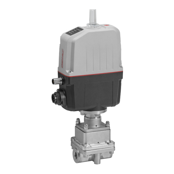
Motorized control valve
Hide thumbs
Also See for 566:
- Operating instructions manual (57 pages) ,
- Operating instructions manual (21 pages) ,
- Operating instructions manual (116 pages)

Related Manuals for GEM 566


Summary of Contents for GEM 566
- Page 1 GEMÜ 566 Elektromotorisch betätigtes Regelventil Motorized control valve Betriebsanleitung Operating instructions Weitere Informationen Webcode: GW-566...
- Page 2 Alle Rechte wie Urheberrechte oder gewerbliche Schutzrechte werden ausdrücklich vorbehalten. All rights including copyrights or industrial property rights are expressly reserved. Dokument zum künftigen Nachschlagen aufbewahren. Keep the document for future reference. © GEMÜ Gebr. Müller Apparatebau GmbH & Co. KG 15.05.2020 2 / 112 GEMÜ 566...
-
Page 3: Table Of Contents
Verwendete Symbole ......... LED-Symbole ............Begriffsbestimmungen ........Warnhinweise ............. 2 Sicherheitshinweise ..........3 Produktbeschreibung ..........4 GEMÜ CONEXO ............5 Bestimmungsgemäße Verwendung ......6 Bestelldaten .............. 7 Technische Daten ............. 8 Abmessungen ............12 9 Herstellerangaben ............. 15 Lieferung ............. 15 Verpackung ............ -
Page 4: Allgemeines
LED-Zustände Symbol Bedeutung Explosionsgefahr Leuchtet Blinkt Aggressive Chemikalien! 1.4 Begriffsbestimmungen Betriebsmedium Medium, das durch das GEMÜ Produkt fließt. Heiße Anlagenteile! 1.5 Warnhinweise Warnhinweise sind, soweit möglich, nach folgendem Schema gegliedert: SIGNALWORT Mögliches Art und Quelle der Gefahr gefahren- Mögliche Folgen bei Nichtbeachtung. -
Page 5: Sicherheitshinweise
Bei Betrieb: 9. Dokument am Einsatzort verfügbar halten. 10. Sicherheitshinweise beachten. 11. Das Produkt gemäß diesem Dokument bedienen. 12. Das Produkt entsprechend der Leistungsdaten betreiben. 13. Das Produkt ordnungsgemäß instand halten. 14. Wartungsarbeiten bzw. Reparaturen, die nicht in dem Do- kument beschrieben sind, nicht ohne vorherige Abstim- mung mit dem Hersteller durchführen. -
Page 6: Gemü Conexo
Das Produkt ist bestimmungsgemäß nicht für den Einsatz in nuelle, pneumatische und elektromotorische Antriebsarten explosionsgefährdeten Bereichen geeignet. zur Verfügung. Das Ventil GEMÜ 566 wurde speziell für die ● Das Produkt gemäß den technischen Daten einsetzen. Regelung von Kleinmengen entwickelt und erlaubt einen Durchfluss von 63 l/h bis zu 2500 l/h. -
Page 7: Bestelldaten
ASTM A 351 CF3M, Feinguss 6 Dichtwerkstoff 7 Spannung/Frequenz 24 V DC 8 Regelmodul Stellungsregler 9 Regelkurve modifiziert gleichprozentig 10 Kv-Wert 63 l/h 11 Antriebsausführung Antriebsgröße 0 12 CONEXO integrierter RFID-Chip zur elektronischen Identifizierung und Rückverfolgbarkeit 7 / 112 www.gemu-group.com GEMÜ 566... -
Page 8: Technische Daten
Kv-Werte: Hub [%] Gleichprozentig (Anschluss-Code 1) / Linear (Anschluss-Code 1) Regelkurve Sitz Ø [mm] Kv-Wert DN 8 DN 10 DN 15 G, L G, L G, L 1000 G, L 1600 G, L 2500 8 / 112 GEMÜ 566 www.gemu-group.com... - Page 9 Auf/Zu Betrieb - Mindestens 500.000 Schaltzyklen bei Raumtemperatur und zulässiger Einschalt- dauer. Mechanische Klasse 4M8 nach EN 60721-3-4:1998 Umweltbedingungen: Vibration: 5g nach IEC 60068-2-6 Test Fc Schocken: 25g nach IEC 60068-2-27 Test Ea 7.6 Elektrische Daten Versorgungsspannung 24 V DC ± 10 % 9 / 112 www.gemu-group.com GEMÜ 566...
- Page 10 Pegel logisch ”0”: < 5,8 V DC Eingangsstrom: typ. < 0,5 mA 7.6.3 Analoge Ausgangssignale Regelmodul Stellungsregler (Code S0) 7.6.3.1 Istwert Ausgangssignal: 0/4 - 20 mA; 0 - 10 V (Funktion über IO-Link wählbar) Ausgangsart: aktiv 10 / 112 GEMÜ 566 www.gemu-group.com...
- Page 11 Min. cycle time: 20 ms (eSyStep Stellungsregler, Code S0) Vendor-ID: Device-ID: 1906801 (eSyStep Stellungsregler, Code S0), Product-ID: eSyStep Positioner (Code S0) ISDU Unterstützung: SIO Betrieb: IO-Link Spezifikation: V1.1 IODD-Dateien können über https://ioddfinder.io-link.com/ oder www.gemu-group.com heruntergeladen werden. 11 / 112 www.gemu-group.com GEMÜ 566...
-
Page 12: Abmessungen
8.1 Einbau- und Antriebsmaße 8.1.1 Ventil mit Gewindemuffe, Code 1 Antriebsaus- führung 32,0 59,4 81,0 133,5 197,7 282,2 117,7 32,0 59,4 81,0 133,5 197,7 282,2 117,7 32,0 59,4 81,0 133,5 197,7 282,2 117,7 Maße in mm 12 / 112 GEMÜ 566 www.gemu-group.com... - Page 13 15,0 9,40 25,0 117,0 33,0 15,0 15,75 25,0 Maße in mm 1) Anschlussart Code 88: Clamp ASME BPE, Baulänge FTF EN 558 Reihe 7 2) Werkstoff Ventilkörper Code C1: ASTM A 351 CF3M, Feinguss 13 / 112 www.gemu-group.com GEMÜ 566...
- Page 14 8 Abmessungen 8.3 Ventilkörperbefestigung 8,10,15,20 Maße in mm 14 / 112 GEMÜ 566 www.gemu-group.com...
-
Page 15: Herstellerangaben
▶ Beschädigung des GEMÜ Produkts. 4. Lösungsmittel, Chemikalien, Säuren, Kraftstoffe u. ä. nicht Schutzmaßnahmen gegen Überschreitung des maximal ● mit GEMÜ Produkten und deren Ersatzteilen in einem zulässigen Drucks durch eventuelle Druckstöße (Was- Raum lagern. serschläge) vorsehen 9.5 Benötigtes Werkzeug VORSICHT 1. -
Page 16: Einbaulage
Klammer verbinden. 5. Alle Sicherheits- und Schutzeinrichtungen wieder anbrin- 10.2 Einbaulage gen bzw. in Funktion setzen. GEMÜ empfiehlt eine senkrecht stehende oder hängende Ein- baulage des Antriebs zur Optimierung der Standzeit. 10.3 Einbau mit Gewindemuffe Abb. 1: Gewindemuffe GEMÜ 566 16 / 112 www.gemu-group.com... -
Page 17: Elektrischer Anschluss
Uv, 24 V DC Versorgungsspannung Digitaleingang 1 Digitaleingang 2 Digitalein- / ausgang Digitalausgang, IO-Link n.c. Anschluss X2 (nur bei Regelmodul Code S0) 5-poliger M12-Einbaustecker, A-kodiert Signalname I+/U+, Sollwerteingang I-/U-, Sollwerteingang I+/U+, Istwertausgang I-/U-, Istwertausgang n.c. 17 / 112 www.gemu-group.com GEMÜ 566... - Page 18 4 – 20 mA 0 – 20 mA 0 – 10 V Analogausgang 4 – 20 mA 4 – 20 mA 4 – 20 mA 4 – 20 mA 0 – 20 mA 0 – 10 V 18 / 112 GEMÜ 566 www.gemu-group.com...
-
Page 19: Spezifische Daten Io-Link (Pin 6)
Steckverbinder und die Stromaufnahme des Antriebs sind nicht konform zur IO-Link Spezifikation. 12.1 Betrieb an IO-Link 12.1.1 Betrieb an SPS als 24 V Gerät Der elektromotorische Antrieb GEMÜ eSyStep kann ohne Einschränkungen direkt an einer SPS-Steuerung betrieben werden. Technische Daten des Produkts und der SPS müssen eingehalten werden. Position... - Page 20 2. Pin 4 (CQ) des Masters mit Pin 6 des Produkts verbinden. Im IO-Link Betrieb kann Pin 6 nicht als Ausgangssignal von der SPS-Steuerung ausgewertet werden. Position Benennung eSyStep SPS mit Versorgungsspannung USB IO-Link Master USB-Schnittstelle Netzstecker Laptop 20 / 112 GEMÜ 566 www.gemu-group.com...
- Page 21 GND der beiden Spannungsversorgungen verbunden ist. In dem Fall erfolgt der Anschluss des Masters wie bei gleicher Span- nungsversorgung ● Pin 4 (CQ) IO-Link Master mit Pin 6 des Produkts verbinden. Pin 3 (L-) IO-Link Master nicht anschließen. (L-) Position Benennung eSyStep B1 und B2 Versorgungsspannungen USB IO-Link Master 21 / 112 www.gemu-group.com GEMÜ 566...
-
Page 22: Prozessdaten
0 → Process valve not in Closed position 1 → Process valve in Closed position Operating mode 0 → Normal operation 1 → Initialization mode Valve position analog 8 … 23 Position of the valve in the range 0 … 1000 22 / 112 GEMÜ 566 www.gemu-group.com... -
Page 23: Parameterübersicht
Gerätename aus- „eSyStep lesen Positioner“ 0x13 Product ID Produkt ID ausle- „eSyStep Positioner“ 0x15 Serial number Seriennummer „XXXXXXXX/YYYY“ auslesen 0x16 Hardware revision Hardware Version „Rev. XX/XX“ auslesen 0x17 Firmware revision Softwareversion „V X.X.X.X.“ auslesen 23 / 112 www.gemu-group.com GEMÜ 566... - Page 24 0 → Active high len Eingang 2 kon- 1 → Active low figurieren R / W Input / output 1 Logischen Digita- 0 → Active high len Eingang / Aus- 1 → Active low gang konfigurieren 24 / 112 GEMÜ 566 www.gemu-group.com...
- Page 25 0 … 4095 peratursensor Set value (W) Analogwert Soll- 0 … 4095 wertsignal 0x62 Operating times Open Stellzeit AUF 0 … 255 (0 … 25,5s) Close Stellzeit ZU 0 … 255 (0 … 25,5s) 25 / 112 www.gemu-group.com GEMÜ 566...
- Page 26 Signalausgang 0 → 0 … 20 mA festlegen 1 → 4 … 20 mA 2 → 0 … 10 V R / W Minimalen Signal- 0 … Max ausgang festlegen (0,0 % … Max) 26 / 112 GEMÜ 566 www.gemu-group.com...
- Page 27 12 Spezifische Daten IO-Link (Pin 6) Sub- Indexname Parameter Funktion Werks- Einstellmöglich- gangs- einstellungen keiten rechte R / W Maximalen Signal- 1000 Min … 1000 ausgang festlegen (Min … 100 %) 27 / 112 www.gemu-group.com GEMÜ 566...
-
Page 28: Parameter
Data storage index 0x03 R / W 1 Byte Data Storage Cmd UIntegerT8 1 Byte State Property UIntegerT8 4 Byte Data Storage Size UIntegerT32 4 Byte Parameter Checks- UIntegerT32 41 Byte Index List Octet- StringT 28 / 112 GEMÜ 566 www.gemu-group.com... - Page 29 Length Indexname Parameter Type Values Rights Profile 0x0D 8 Byte ArrayT 0x8000 Characteristics 0x8002 0x8003 0x8100 Beschreibung Parameterwerte Indexname Parameter Werte Beschreibung Profile Characteristics 0x8000 Geräte-Identifikation Objekte 0x8002 Prozessdatenabbildung 0x8003 Diagnose 0x8100 Externe Identifikation 29 / 112 www.gemu-group.com GEMÜ 566...
- Page 30 StringT "GEMUE" 12.4.8 Product name Mit dem Parameter Product name kann der Gerätename im ASCII Format ausgelesen werden. Off- Access Length Indexname Parameter Type Values Rights Product name 0x12 18 Byte StringT "eSyStep Positioner" 30 / 112 GEMÜ 566 www.gemu-group.com...
- Page 31 Mit dem Parameter Application specific tag kann ein 32 Zeichen langer Text im Gerät gespeichert werden. Zum Beispiel Einbauort, Funktion, Einbau-Datum..Off- Access Length Indexname Parameter Type Values Rights Application 0x18 R / W 32 Byte StringT „**************** " specific tag 31 / 112 www.gemu-group.com GEMÜ 566...
- Page 32 IO-Link Events (siehe Kapitel 12.5 Events). Off- Access Length Indexname Parameter Type Values Rights Detailed Device 0x25 39 Byte ArrayT Siehe Kapitel 12.5 Events Status Beschreibung Parameterwerte Indexname Parameter Werte Beschreibung Detailed Device Status Siehe Kapitel 12.5 Events 32 / 112 GEMÜ 566 www.gemu-group.com...
- Page 33 Mit dem Parameter Function digital inputs können Funktionen der digitalen Eingänge konfiguriert werden. Off- Access Lengt Indexname Parameter Type Default Values Rights Function digital 0x4B R / W 3 Bit Input 1 uint:8 inputs R / W 3 Bit Input 2 uint:8 33 / 112 www.gemu-group.com GEMÜ 566...
- Page 34 Bei aktivem Signal arbeitet das Gerät normal. Bei Wegfall des Signals fährt das Gerät in Sicherheitsstellung. Die Sicherheitsstellung wird mittels des Parameters Error Action (Index 0x4F (siehe 'Error Action')) definiert. (Init) Eingang kann als Initialisierungs-Eingang verwendet werden. 34 / 112 GEMÜ 566 www.gemu-group.com...
- Page 35 (Output Error & Warning) Fehler und Warnungen ausgeben. (Input Init) Ein- / Ausgang als Initialisierungseingang konfigurieren. (Push-Pull) Ausgang als Push-Pull konfigurieren. Type in- / output (NPN) Ausgang als NPN konfigurieren. (PNP) Ausgang als PNP konfigurieren. 35 / 112 www.gemu-group.com GEMÜ 566...
- Page 36 Input 2 (Active low) Eingang 2 invertiert. (Active high) Ein- / Ausgang nicht invertiert. Input / output 1 (Active low) Ein- / Ausgang invertiert. (Active high) Ausgang nicht invertiert. Output 2 (Active low) Ausgang invertiert. 36 / 112 GEMÜ 566 www.gemu-group.com...
- Page 37 Error action Error action Stellung stehen. (Open) Antrieb fährt bei einem Fehler in Stellung AUF. (Close) Antrieb fährt bei einem Fehler in Stellung ZU. Error time 1 … 1000 Zeitverzögerung zwischen Fehlererkennung und Fehlermeldung festlegen. 37 / 112 www.gemu-group.com GEMÜ 566...
- Page 38 (Disabled) Vor-Ort-Initialisierung (siehe 'Initialisierung', Seite 47) deaktiviert. Operating mode Betriebsmodus für Stellungsregler aktiviert. Betriebsmodus für AUF/ZU-Steuerung aktiviert. (Disabled) Verwendung von IO-Link Prozessdaten (siehe IO-Link process data ProzessdatenSeite 22) ist deaktiviert. (Enabled) Verwendung von IO-Link Prozessdaten (siehe ProzessdatenSeite 22) ist aktiviert. 38 / 112 GEMÜ 566 www.gemu-group.com...
- Page 39 0 … 4092 Beschreibung Parameterwerte Indexname Parameter Werte Beschreibung Initialized positions Open 0 … 4092 Analogwert Ventilstellung AUF Close 0 … 4092 Analogwert Ventilstellung ZU Stroke 0 … 4092 Analogwert Hub (Differenz zwischen AUF und ZU). 39 / 112 www.gemu-group.com GEMÜ 566...
- Page 40 Aktuellen Analogwert des Potentiometers auslesen. Supply voltage 0 … 4095 Aktuellen Analogwert der Versorgungsspannung auslesen. Temperature 0 … 4095 Aktuellen Analogwert des Temperatursensors auslesen. Set value (W) 0 … 4095 Aktuellen Analogwert des Sollwerts auslesen. 40 / 112 GEMÜ 566 www.gemu-group.com...
- Page 41 Kraft des Ventils einstellen. Werkseitig je nach Ventiltyp voreingestellt. Force initialization 1 … 6 Kraft während der Initialisierung einstellen. Werksseitig je nach Ventiltyp voreingestellt. Krafteinstellungen Antriebsgröße Einstellparameter Kraft AG0 und AG1 Kleinste Kraft Maximale Kraft 41 / 112 www.gemu-group.com GEMÜ 566...
- Page 42 Beschreibung Parameterwerte Indexname Parameter Werte Beschreibung Open / close tight Open tight 800 … 1000 Dichtschließfunktion Ventilposition AUF einstellen. (80,0 … 100,0 Close tight 0 … 200 Dichtschließfunktion Ventilposition ZU einstellen. (0 … 20,0 %) 42 / 112 GEMÜ 566 www.gemu-group.com...
- Page 43 Min Pos … Hubbegrenzung des Regelbereichs in Ventilposition AUF 1000 einstellen. (Min Pos … 100,0 %) Min pos 0 … Max Pos Hubbegrenzung des Regelbereichs in Ventilposition ZU (0,0 % … Max einstellen. Pos) 43 / 112 www.gemu-group.com GEMÜ 566...
- Page 44 Wert überschritten, kommt die Meldung „Sollwert zu groß“. U max 100 … 110 Maximalen Wert des Spannungseingangs festlegen. Wird (10,0 … 11,0 V) der eingestellte Wert überschritten, kommt die Meldung „Sollwert zu hoch. 44 / 112 GEMÜ 566 www.gemu-group.com...
-
Page 45: Events
Event Beschreibung Möglicher Grund Fehlerbehebung Device Hardware Fault Das Event tritt auf, wenn ein Defekt der Erfassung der GEMÜ Support kontaktieren 0x5000 Hardware-Defekt erkannt wird. Ventilstellung. Parameter beim Einschalten des Geräts nicht mehr lesbar. Motor Unable To Move Das Event tritt auf, wenn der Ventil ist blockiert (zum Ventil prüfen... - Page 46 Ventilstellung gelesen wird, Ventilposition. die in Richtung „Open“ nie Fehler beim Tausch einer erreicht werden kann. Membrane (Hub des Ventils im falschen Bereich). Antrieb wurde falsch auf Ventil aufgebaut (Hub des Ventils im falschen Bereich). 46 / 112 GEMÜ 566 www.gemu-group.com...
-
Page 47: Bedienung
ð Gegen Uhrzeigersinn drehen, um das Ventil zu öffnen. ð LEDs OPEN und CLOSED blinken alternierend. 2. Ventil fährt automatisch in Stellung AUF. 3. Ventil fährt automatisch in Stellung ZU. 4. Initialisierungsmodus wird automatisch beendet. 5. Endlagen sind eingestellt. www.gemu-group.com 47 / 112 GEMÜ 566... -
Page 48: Inspektion Und Wartung
2. Antrieb A auf Regelmechanik 4 setzen. 5. Anlage bzw. Anlagenteil drucklos schalten. 3. Unterlegscheiben 27 über Stiftschrauben 25 legen. 6. GEMÜ Produkte, die immer in derselben Position sind, viermal pro Jahr betätigen. 4. Befestigungselemente handfest einschrauben und mit geeignetem Gabelschlüssel über Kreuz festziehen (Dreh- 7. -
Page 49: Regelkegel Austauschen
8. Ventilspindel 21 und Regelkegel 3 mit montierter Trenn- membrane 2 nach unten herausziehen. 7. Sicherungsring 28 entfernen. ð Druckfeder 23 steht unter Spannung. 8. Ventilspindel 21 und Regelkegel 3 mit montierter Trenn- membrane 2 nach unten herausziehen. www.gemu-group.com 49 / 112 GEMÜ 566... -
Page 50: Trennmembrane Austauschen
Teile dabei nicht beschädigen. Danach Teile auf Be- handfest montieren. schädigung prüfen. Wenn Teile beschädigt sind, diese 7. Innensechskantschrauben 6 über Kreuz festziehen. dann auswechseln. 14.5.2 Demontage mit Montagewerkzeug 1. Regelkegel demontieren (siehe Kapitel Demontage Regel- kegel). GEMÜ 566 50 / 112 www.gemu-group.com... - Page 51 14.6 Reinigung des Produkts gen. Teile dabei nicht beschädigen. Danach Teile auf Be- schädigung prüfen. Wenn Teile beschädigt sind, diese – Das Produkt mit feuchtem Tuch reinigen. dann auswechseln. Das Produkt nicht mit Hochdruckreiniger reinigen. – www.gemu-group.com 51 / 112 GEMÜ 566...
-
Page 52: Fehlerbehebung
Open und Closed blinken alternierend Temperatur Fehler Betrieb Notstrom, Stellung AUF Betrieb Notstrom, Stellung ZU Betrieb Notstrom, Stellung unbekannt Sollwert zu klein Sollwert zu groß Wartung nötig, Stellung AUF Wartung nötig, Stellung ZU Wartung nötig, Stellung unbekannt GEMÜ 566 52 / 112 www.gemu-group.com... - Page 53 Befestigungsteile lose Befestigungsteile nachziehen Antriebsflansch und Ventilkörper undicht Ventilkörper / Antrieb beschädigt Ventilkörper / Antrieb austauschen Körper des GEMÜ Produkts undicht Körper des GEMÜ Produkts defekt oder Körper des GEMÜ Produkts auf korrodiert Beschädigungen prüfen, ggf. Körper tauschen Unsachgemäße Montage Montage Ventilkörper in Rohrleitung...
-
Page 54: Ausbau Aus Rohrleitung
Entsorgung. 1. Das Produkt reinigen. 1. Auf Restanhaftungen und Ausgasung von eindiffundier- ten Medien achten. 2. Rücksendeerklärung bei GEMÜ anfordern. 2. Alle Teile entsprechend der Entsorgungsvorschriften / 3. Rücksendeerklärung vollständig ausfüllen. Umweltschutzbedingungen entsorgen. 4. Das Produkt mit ausgefüllter Rücksendeerklärung an GEMÜ... -
Page 55: Konformitätserklärung Nach 2014/68/Eu (Druckgeräterichtlinie)
Die Produkte werden entwickelt und produziert nach GEMÜ eigenen Verfahrensanweisungen und Qualitätsstandards, welche die Forderungen der ISO 9001 und der ISO 14001 erfüllen. Die Produkte dürfen gemäß Artikel 4, Absatz 3 der Druckgeräterichtlinie 2014/68/EU keine CE-Kennzeichnung tragen. Ingelfingen-Criesbach, 2020-03-13 ppa. Joachim Brien... -
Page 56: Konformitätserklärung Nach 2014/30/Eu (Emv-Richtlinie)
20 Konformitätserklärung nach 2014/30/EU (EMV-Richtlinie) 20 Konformitätserklärung nach 2014/30/EU (EMV-Richtlinie) EU-Konformitätserklärung gemäß 2014/30/EU (EMV-Richtlinie) GEMÜ Gebr. Müller Apparatebau GmbH & Co. KG Wir, die Firma Fritz-Müller-Straße 6-8 D-74653 Ingelfingen-Criesbach erklären, dass das unten aufgeführte Produkt die Sicherheitsanforderungen der EMV-Richtlinie 2014/30/EU erfüllt. - Page 57 Definition of terms ..........58 Warning notes ............ 58 2 Safety information ............ 59 3 Product description ........... 59 4 GEMÜ CONEXO ............60 5 Correct use ............... 60 6 Order data ..............61 7 Technical data ............62 8 Dimensions ............... 66 9 Manufacturer's information ........
-
Page 58: General Information
Lit (on) Flashing Hot plant components! 1.4 Definition of terms Working medium The medium that flows through the GEMÜ product. 1.5 Warning notes Wherever possible, warning notes are organised according to the following scheme: SIGNAL WORD Type and source of the danger... -
Page 59: Safety Information
13. Maintain the product correctly. 14. Do not carry out any maintenance work and repairs not described in this document without consulting the manu- facturer first. In cases of uncertainty: 15. Consult the nearest GEMÜ sales office. www.gemu-group.com 59 / 112 GEMÜ 566... -
Page 60: Gemü Conexo
The product is designed for installation in piping systems and for controlling a working medium. The GEMÜ 566 2/2-way straight seat control valve has a body with an integrated control mechanism. Manual, pneu- The product is not intended for use in potentially explosive matic and motorized actuator types are available. -
Page 61: Order Data
7 Voltage/frequency 24 V DC 8 Control module Positioner 9 Control characteristic Modified equal-percentage 10 Kv value 63 l/h 11 Actuator version Actuator size 0 12 CONEXO Integrated RFID chip for electronic identification and traceability 61 / 112 www.gemu-group.com GEMÜ 566... -
Page 62: Technical Data
Equal-percentage (connection code 1) / linear (connection code 1) Control char- Seat Ø [mm] Kv value DN 8 DN 10 DN 15 acteristic G, L G, L G, L 1000 G, L 1600 G, L 2500 62 / 112 GEMÜ 566 www.gemu-group.com... - Page 63 Class 4M8 acc. to EN 60721-3-4:1998 environmental conditions: Vibration: 5g acc. to IEC 60068-2-6 Test Fc Shock: 25g acc. to 60068-2-27 Test Ea 7.6 Electrical data Supply voltage Uv: 24 V DC ± 10% 63 / 112 www.gemu-group.com GEMÜ 566...
- Page 64 < 5.8 V DC Input current: typically < 0.5 mA 7.6.3 Analogue output signals – Control module Positioner (code S0) 7.6.3.1 Actual value Output signal: 0/4 - 20 mA; 0 - 10 V (function selectable via IO-Link) 64 / 112 GEMÜ 566 www.gemu-group.com...
- Page 65 20 ms (eSyStep positioner, code S0) Vendor-ID: Device-ID: 1906801 (eSyStep positioner, code S0), Product-ID: eSyStep Positioner (code S0) ISDU support: SIO operation: IO-Link specification: V1.1 IODD files can be downloaded via https://ioddfinder.io-link.com/ or www.gemu-group.com. 65 / 112 www.gemu-group.com GEMÜ 566...
-
Page 66: Dimensions
8.1.1 Valve with threaded sockets, code 1 Actuator ver- sion 32.0 59.4 81.0 133.5 197.7 282.2 117.7 32.0 59.4 81.0 133.5 197.7 282.2 117.7 32.0 59.4 81.0 133.5 197.7 282.2 117.7 Dimensions in mm 66 / 112 GEMÜ 566 www.gemu-group.com... - Page 67 33.0 15.2 15.75 25.0 Dimensions in mm 1) Connection type Code 88: Clamp ASME BPE, face-to-face dimension FTF EN 558 series 7 2) Valve body material Code C1: ASTM A 351 CF3M, investment casting 67 / 112 www.gemu-group.com GEMÜ 566...
- Page 68 8 Dimensions 8.3 Valve body mounting 8,10,15,20 Dimensions in mm 68 / 112 GEMÜ 566 www.gemu-group.com...
-
Page 69: Manufacturer's Information
▶ Damage to the GEMÜ product. 4. Do not store solvents, chemicals, acids, fuels or similar Provide precautionary measures against exceeding the ● fluids in the same room as GEMÜ products and their maximum permitted pressures caused by pressure spare parts. surges (water hammer). -
Page 70: Installation Position
14. Please note the flow direction. 15. Please note the installation position (see chapter "Install- ation position"). 10.2 Installation position GEMÜ recommend installing the actuator vertically upright or vertically down to optimise the service life. 10.3 Installation with threaded sockets Fig. 1: Threaded socket... -
Page 71: Electrical Connection
Connection X2 (only for control module code S0) 5-pin M12 plug, A-coded Signal name I+/U+, set value input I-/U-, set value input I+/U+, actual value output I-/U-, actual value output n. c. 71 / 112 www.gemu-group.com GEMÜ 566... - Page 72 0 – 20 mA 0 – 10 V Analogue output 4 – 20 mA 4 – 20 mA 4 – 20 mA 4 – 20 mA 0 – 20 mA 0 – 10 V 72 / 112 GEMÜ 566 www.gemu-group.com...
-
Page 73: Specific Data Io-Link (Pin 6)
12.1 Operation on IO-Link 12.1.1 Operation on PLC as a 24 V device The motorized actuator GEMÜ eSyStep can be operated directly in a PLC control unit without limitations. Technical data of the product and of PLC must be complied with. - Page 74 2. Connect pin 4 (CQ) of the master with pin 6 of the product. During IO-Link operation, pin 6 cannot be evaluated by the PLC control unit as an output signal. Item Name eSyStep PLC with supply voltage USB IO-Link Master USB interface Mains plug – laptop 74 / 112 GEMÜ 566 www.gemu-group.com...
- Page 75 In this case, the master is connected as when the power supply is identical ● Connect pin 4 (CQ) IO-Link master with pin 6 of the product. Do not connect (pin 3) L- IO-Link master. (L-) Item Name eSyStep B1 and B2 Supply voltages USB IO-Link Master 75 / 112 www.gemu-group.com GEMÜ 566...
-
Page 76: Process Data
0 → Process valve not in Closed position 1 → Process valve in Closed position Operating mode 0 → Normal operation 1 → Initialization mode Valve position analog 8 … 23 Position of the valve in the range 0 … 1000 76 / 112 GEMÜ 566 www.gemu-group.com... -
Page 77: Parameter Overview
Product ID Read out product "eSyStep Positioner" 0x15 Serial number Read out serial "XXXXXXXX/YYYY" number 0x16 Hardware revision Read out hard- "Rev. XX/XX" ware version 0x17 Firmware revision Read out software "V X.X.X.X." version 77 / 112 www.gemu-group.com GEMÜ 566... - Page 78 1 → Active low Input / output 1 Configure logical 0 → Active high digital input/out- 1 → Active low Output 2 Configure logical 0 → Active high digital output 1 → Active low 78 / 112 GEMÜ 566 www.gemu-group.com...
- Page 79 Operating times Open Operating time 0 to 255 OPEN (0 to 25.5s) Close Operating time 0 to 255 CLOSE (0 to 25.5s) 0x90 Drive sets Force Force, dependent 1 … 6 on valve used 79 / 112 www.gemu-group.com GEMÜ 566...
- Page 80 Type Determine signal 0 → 0 to 20 mA output 1 → 4 to 20 mA 2 → 0 to 10 V Min. Determine min- 0 to Max imum signal out- (0.0% to Max) 80 / 112 GEMÜ 566 www.gemu-group.com...
- Page 81 12 Specific data IO-Link (pin 6) Sub- Access Index name Parameter Function Factory Setting options rights settings Determine max- 1000 Min to 1000 imum signal out- (Min to 100%) 81 / 112 www.gemu-group.com GEMÜ 566...
-
Page 82: Parameter
Type Values Rights Data storage index 0x03 1 byte Data Storage Cmd UIntegerT8 1 byte State Property UIntegerT8 4 bytes Data Storage Size UIntegerT32 4 bytes Parameter Check- UIntegerT32 Index List Octet- bytes StringT 82 / 112 GEMÜ 566 www.gemu-group.com... - Page 83 Profile 0x0D 8 bytes ArrayT 0x8000 Characteristics 0x8002 0x8003 0x8100 Description of parameter values Index name Parameter Values Description Profile Characteristics 0x8000 Device identification objects 0x8002 Process data mapping 0x8003 Diagnostics 0x8100 External identification 83 / 112 www.gemu-group.com GEMÜ 566...
- Page 84 12.4.8 Product name The device name can be read out in ASCII format with the Product name parameter. Off- Access Length Index name Parameter Type Values Rights Product name 0x12 18 byte StringT "eSyStep Positioner" 84 / 112 GEMÜ 566 www.gemu-group.com...
- Page 85 A text with 32 characters can be stored in the device with the Application specific tag parameter. For example, installation location, function, installation date, etc. Off- Access Length Index name Parameter Type Values Rights Application 0x18 StringT „**************** " specific tag bytes 85 / 112 www.gemu-group.com GEMÜ 566...
- Page 86 Length Index name Parameter Type Values Rights Detailed Device 0x25 39 byte ArrayT See chapter 12.5 Events Status Description of parameter values Index name Parameter Values Description Detailed Device Status See chapter 12.5 Events 86 / 112 GEMÜ 566 www.gemu-group.com...
- Page 87 The functions of the digital inputs can be configured with the Function digital inputs parameter. Off- Access Lengt Index name Parameter Type Default Values Rights Function digital 0x4B 3 bits Input 1 uint:8 inputs 3 bits Input 2 uint:8 87 / 112 www.gemu-group.com GEMÜ 566...
- Page 88 If there is no signal, the device moves into the safety position. The safety position is defined by the parameter Error Action (index 0x4F (see "Error Action'"). (Init) Input can be used as an initialization input. 88 / 112 GEMÜ 566 www.gemu-group.com...
- Page 89 (Output Error & Warning) Output error and warnings. (Input Init) Configure input/output as initialization input. (Push-Pull) Configure output as Push-Pull. Type in- / output (NPN) Configure output as NPN. (PNP) Configure output as PNP. 89 / 112 www.gemu-group.com GEMÜ 566...
- Page 90 (Active high) Input 2 not inversed. Input 2 (Active low) Input 2 inversed. (Active high) Input/output not inversed. Input / output 1 (Active low) Input/output inversed. (Active high) Output not inversed. Output 2 (Active low) Output inversed. 90 / 112 GEMÜ 566 www.gemu-group.com...
- Page 91 (Open) Actuator moves to the OPEN position in case of an error. (Close) Actuator moves to the CLOSED position in case of an error. Error time 1 … 1000 Determine delay time between error detection and error message. 91 / 112 www.gemu-group.com GEMÜ 566...
- Page 92 Operating mode for positioner activated. Operating mode for OPEN/CLOSE control activated. (Disabled) Use of IO-Link process data (see “Process data“, IO-Link process data page 76) is deactivated. (Enabled) Use of IO-Link process data (see “Process data“, page 76) is activated. 92 / 112 GEMÜ 566 www.gemu-group.com...
- Page 93 Values Description Initialized positions Open 0 … 4092 Analog value valve position OPEN Close 0 … 4092 Analog value valve position CLOSED Stroke 0 … 4092 Analog value stroke (difference between OPEN and CLOSED). 93 / 112 www.gemu-group.com GEMÜ 566...
- Page 94 Read out current analog value of the supply voltage. Temperature 0 … 4095 Read out current analog value of the temperature sensor. Set value (W) 0 … 4095 Read out current analog value of the set value. 94 / 112 GEMÜ 566 www.gemu-group.com...
- Page 95 Force initialization 1 … 6 Set the force during initialization. Preset at the factory depending on the valve type. Force settings Actuator size Setting parameter Force AG0 and AG1 Minimum force Maximum force 95 / 112 www.gemu-group.com GEMÜ 566...
- Page 96 Open / close tight Open tight 800 … 1000 Set the sealing function valve position OPEN. (80.0 … 100.0 Close tight 0 … 200 Set the sealing function valve position CLOSED. (0 … 20.0 %) 96 / 112 GEMÜ 566 www.gemu-group.com...
- Page 97 Set the stroke limiter of the control range in valve position 1000 OPEN. (Min Pos to 100.0%) Min pos 0 to Max Pos Set the stroke limiter of the control range in valve position (0.0% to Max CLOSED. Pos) 97 / 112 www.gemu-group.com GEMÜ 566...
- Page 98 "Set value too high" is issued. U max 100 to 110 Determine maximum value of the voltage input. If the set (10.0 to 11.0 V) value is exceeded, the message "Set value too high" is issued. 98 / 112 GEMÜ 566 www.gemu-group.com...
-
Page 99: Events
Event Description Possible cause Troubleshooting Device Hardware Fault The event occurs when a Fault in valve position Contact GEMÜ Support 0x5000 hardware fault is detected. detection. Parameter can no longer be read when switching the device on. Motor Unable To Move... - Page 100 Error when replacing a "Open" direction. diaphragm (stroke of the valve in incorrect area). Actuator has been fitted on the valve incorrectly (stroke of the valve in the incorrect area). 100 / 112 GEMÜ 566 www.gemu-group.com...
-
Page 101: Operation
ð Turn anticlockwise to open the valve. 2. Valve automatically moves into the OPEN position. 3. Valve automatically moves into the CLOSED position. 4. Initialization mode is automatically ended. 5. The end positions are set. www.gemu-group.com 101 / 112 GEMÜ 566... -
Page 102: Inspection And Maintenance
14.3 Mounting the actuator 5. Depressurize the plant or plant component. 6. Actuate GEMÜ products which are always in the same 1. Move the actuator A to the open position. position four times a year. 2. Place actuator A onto control mechanism 4. -
Page 103: Replacing The Regulating Cone
7. Remove the circlip 28. ð Compression spring 23 is under tension. 8. Remove the valve spindle 21 and regulating cone 3 with the mounted isolating diaphragm 2 by withdrawing them downwards. www.gemu-group.com 103 / 112 GEMÜ 566... -
Page 104: Replacing The Isolating Diaphragm
If parts are damaged, 7. Fully tighten the hexagon socket screws 6 diagonally. replace them. 14.5.2 Disassembly with assembly tool 1. Remove the regulating cone (see chapter "Removing the regulating cone"). GEMÜ 566 104 / 112 www.gemu-group.com... - Page 105 If parts are damaged, regulating cone"). replace them. 14.6 Cleaning the product – Clean the product with a damp cloth. Do not clean the product with a high pressure clean- – ing device. www.gemu-group.com 105 / 112 GEMÜ 566...
-
Page 106: Troubleshooting
Emergency power operation, OPEN position Emergency power operation, CLOSED position Emergency power operation, position unknown Set value too small Set value too high Maintenance required, OPEN position Maintenance required, CLOSED position Maintenance required, position unknown GEMÜ 566 106 / 112 www.gemu-group.com... - Page 107 Valve body / actuator damaged Replace valve body/actuator Body of the GEMÜ product is leaking Body of the GEMÜ product is faulty or Check the body of the GEMÜ product for corroded potential damage, replace body if...
-
Page 108: Removal From Piping
3. Disassemble the product. Observe warning notes and goods can be processed only when this note is completed. If safety information. no return delivery note is included with the product, GEMÜ cannot process credits or repair work but will dispose of the 17 Disposal goods at the operator's expense. -
Page 109: Declaration Of Conformity According To 2014/68/Eu (Pressure Equipment Directive)
EN 1983, AD 2000 Note for products with a nominal size ≤ DN 25: The products are developed and produced according to GEMÜ process instructions and quality standards which comply with the requirements of ISO 9001 and ISO 14001. According to Article 4, Paragraph 3 of the Pressure Equipment Directive 2014/68/EU these products must not be identified by a CE-label. -
Page 110: Declaration Of Conformity According To 2014/30/Eu (Emc Directive)
20 Declaration of conformity according to 2014/30/EU (EMC Directive) EU Declaration of Conformity according to 2014/30/EU (EMC Directive) GEMÜ Gebr. Müller Apparatebau GmbH & Co. KG Fritz-Müller-Straße 6-8 74653 Ingelfingen-Criesbach, Germany declare that the product listed below complies with the safety requirements of the EMC Directive 2014/30/EU. - Page 111 111 / 112 GEMÜ 566 www.gemu-group.com...
- Page 112 GEMÜ Gebr. Müller Apparatebau GmbH & Co. KG Fritz-Müller-Straße 6-8, 74653 Ingelfingen-Criesbach, *88695936* Subject to alteration Germany 05.2020 | 88695936 Phone +49 (0)7940 123-0 · info@gemue.de www.gemu-group.com...