
Related Manuals for Vallox A3609


Summary of Contents for Vallox A3609
- Page 1 Model Document Vallox TSK Multi 50 MV D5321 Vallox TSK Multi 50 MV EH Vallox TSK Multi 80 MV Valid from Vallox TSK Multi 80 MV EH 7.3.2022 Type Updated A3609 20.06.2022 A3609-1 C3608 C3608-1 Manual Ventilation units...
-
Page 2: Table Of Contents
Main parts ..............6 Vallox TSK Multi 50 MV and Vallox TSK Multi 80 MV......6 INSTALLATION . -
Page 3: Safety
INTENDED USE All Vallox ventilation units have been designed to provide appropriate and continuous ventilation so as to present no threat to health and to maintain structures in good condition. IMPORTANT In order to ensure that the indoor air presents no harm to health and remains optimal also for the structures of the building, ventilation must be kept on without disruptions. -
Page 4: Safety Signs Used In The Instructions
INSTALLATION OPTIONS NOTE The standard equipment and • Vallox TSK Multi 50 MV and Vallox TSK Multi 80 MV are available accessories designed to be mounted above a false ceiling. vary from country to country. SYSTEM DESCRIPTION Internet 2. -
Page 5: Ventilation Unit Control
For the MyVallox Cloud/ Home instructions, Ventilation unit control options please go to vallox.techmanuals.info/ Operation of the Vallox ventilation unit can be controlled by the ValloxMV/ENG/help/ following means: webhelp • Through the My Vallox Control panel installed in the building. -
Page 6: Main Parts
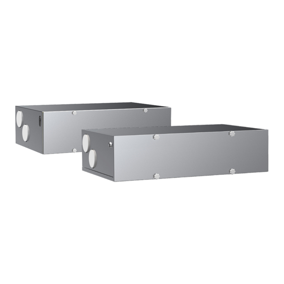
MAIN PARTS Vallox TSK Multi 50 MV and Vallox TSK Multi 80 MV R model in the figure Supply air fan Extract air fan Safety switch Post-heating resistor Control panel Heat recovery cell Internal humidity sensor Fine filter for supply air... -
Page 7: Installation Site
(e.g. storage premises, technical spaces, and false ceilings). Vallox TSK Multi 50 MV and Vallox TSK Multi 80 MV must be mounted on the ceiling. Use the mounting hooks (4 pcs) delivered with the unit to mount the ventilation unit on the ceiling. -
Page 8: Dimensions And Duct Outlets
DIMENSIONS AND DUCT OUTLETS Vallox TSK Multi 50 MV Vallox TSK Multi 80 MV 1026 R model R model R model: Outdoor air to the unit Supply air from the unit to the apartment Extract air from the apartment to the unit... -
Page 9: Maintenance
HR cell bypass damper, and heating resistor is mirrored in the left-handed model. CHANGING THE FILTERS The Vallox ventilation unit has three filters: • Coarse filter for supply air filters insects, heavy pollen and other NOTE relatively large foreign objects out of the outdoor air. -
Page 10: Cleaning The Heat Recovery Cell
CLEANING THE HEAT RECOVERY CELL Check that the heat recovery cell (D) is clean roughly once a year when the filters are being replaced. Clean by washing as required. To check the heat recovery cell (HR cell): Disconnect the ventilation unit from the mains electricity supply. -
Page 11: Cleaning The Fans
NOTE door is touching the safety switch. The steps are mirrored for the left handed unit. 13. Plug the ventilation unit back into the mains. The fan has now been checked and cleaned. © Vallox Oy - All rights reserved... -
Page 12: Cleaning The Extract Air Fan
Cleaning the extract air fan To remove and clean the extract air fan: Disconnect the ventilation unit from the mains electricity supply. 2. Lift the latch to open the door of the ventilation unit. 3. Lift the door off. CAUTION The door is heavy. -
Page 13: Technical Specifications
10 % dm /s E Right side (l/s) m /h Volume flow rate AIR VOLUMES VALLOX TSK MULTI 50 MV, SUPPLY AIR (FINE+COARSE), EXTRACT AIR (COARSE) Pressure loss in ducts. Total pressure (Pa) extract air 100 % supply air 80 %... - Page 14 27/30 31/34 35/40 41/45 44/48 , dB (A) TECHNICAL SPECIFICATIONS Product title Product number Vallox TSK Multi 80 MV R 3530300 Vallox TSK Multi 80 MV L 3530400 Air volumes Fans Supply air 85 dm /s, 100 Pa Supply air 0.081 kW, 0.65 A EC...
- Page 15 10 % dm /s E Right side (l/s) m /h Volume flow rate AIR VOLUMES VALLOX TSK MULTI 80 MV, SUPPLY AIR (FINE+COARSE), EXTRACT AIR (COARSE) Pressure loss in ducts. Total pressure (Pa) 100 % extract air 60 % supply air...
-
Page 16: Internal Electrical Connection
3. Supply air 130°C overheating protection D/I2 Digital input 2 4. Exhaust air (Vallox TSK Multi 50 MV EH / Vallox TSK 5. Supply air from the HR cell 11V1 11.1 V operating voltage Multi 80 MV EH, EHX) AN/I Analog input 0-10VDC Additional heating resistor with 90°C... -
Page 17: External Electrical Connection
RS_A Local hardware Modbus A signal RM/I 24V relay input MyVallox CO sensor MyVallox VOC sensor RS_B Local hardware Modbus B signal RM/O 24V relay output Voltage 24 VDC External temperature sensor connector © Vallox Oy - All rights reserved... -
Page 18: Duct Radiator Operation
DUCT RADIATOR OPERATION Always follow first and foremost the connection diagram provided by the HVAC designer or heat pump manufacturer. If the duct NOTE: Also read the duct radiator manual. radiator is used in the supply air duct, it The accompanying figure shows an example of the can only be used for arrangement for connecting the heating/cooling radiator unit cooling. -
Page 19: Duct Radiator Operation Chart
Feed from the distribution board External electrical junction box for the MV Air extraction External NTC sensor for Vallox MV ventilation units Duct radiator (reverse connection) 24 VDC relay/contactor for controlling the pump and the solenoid valve. Not included in the delivery. -
Page 20: External Electrical Connection For Controlling The Mlv Duct Radiator
EXTERNAL ELECTRICAL CONNECTION FOR CONTROLLING THE MLV DUCT RADIATOR 24 VDC relay/ Distribution board contactor for controlling the pump and solenoid valve +24VDC External temperature sensor NTC 4K7 MLV control Ethernet connection on top of the unit Plug connection 1.2 m on top of the unit VENTILATION UNIT INTERNAL ELECTRICAL CONNECTION RJ45 Female... -
Page 21: Exploded View And Parts List
(Vallox TSK Multi 80 MV) (Vallox TSK Multi 50 MV) HR cell, enthalpy 933151 Filter stand 3356400 (coarse filter for supply air, 500 mm, Vallox TSK Multi 50 MV)) (Vallox TSK Multi 50 MV) Filter stand 3352700 HR cell, plastic 933195... -
Page 22: Conformity Certificates
CONFORMITY CERTIFICATES... - Page 24 Vallox Oy | Myllykyläntie 9-11 | 32200 LOIMAA | FINLAND...
Need help?
Do you have a question about the A3609 and is the answer not in the manual?
Questions and answers