Table of Contents
Advertisement
Quick Links
Advertisement
Table of Contents

Related Manuals for ICRealtime ICIP-D2360


Summary of Contents for ICRealtime ICIP-D2360
- Page 1 HD Panorama Network Camera User’s Manual Version 1.0.0...
- Page 2 Welcome Thank you for purchasing our network camera! This user’s manual is designed to be a reference tool for your system. Please read the following safeguard and warnings carefully before you use this series product! Please keep this user’s manual well for future reference!
- Page 3 Important Safeguards and Warnings 1.Electrical safety All installation and operation here should conform to your local electrical safety codes. The power shall conform to the requirement in the SELV (Safety Extra Low Voltage) and the Limited power source is rated 12V DC in the IEC60950-1. This series product supports PoE too.
- Page 4 6. Daily Maintenance Please shut down the device and then unplug the power cable before you begin daily maintenance work. Do not touch the CCD (CMOS) optic component. You can use the blower to clean the dust on the lens surface. Always use the dry soft cloth to clean the device.
-
Page 5: Table Of Contents
Table of Contents General Introduction ..................... 1 Overview ......................1 Features ......................1 Specifications ....................2 1.3.1 Performance ................... 2 1.3.2 Factory Default Setup ................4 Structure ........................10 Multi-function Combination Cable ..............10 Dimensions ....................10 Bidirectional Talk ..................11 2.3.1 Device-end to PC-end ................ -
Page 6: General Introduction
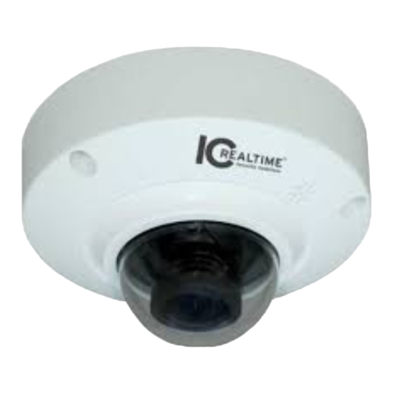
1 General Introduction Overview This series network camera combines traditional camera and network video technology into one unit which integrates A/V data collection and transmission through network without aux devices. It uses standard H.264 and MJPEG video compression technology, which maximally guarantee the audio and video quality. This series network camera enclosure has the strong resistance capacity, which can guarantee the proper work performance under heavy strike. -
Page 7: Specifications
Realize network camera configuration and management via Ethernet. Network Support device management via web or client-end. Management Support various network protocols. External power adapter DC12V Power Warning! Do not connect two power supplying sources to the device at the same time;... - Page 8 Video Compressio H.264/H.264B/MJPEG n Standard PAL: Main stream (1080P@25fps,SXGA@25fps,1.3M@25fps,720P@25fps,D1@25fps) Video Frame Extra stream (D1@25fps,CIF@25fps) Rate NTSC: Main stream (1080P@30fps,SXGA@30fps,1.3M@30fps,720P@30fps,D1@30fps) Extra stream (D1@30fps,CIF@30fps) H.264:56Kbps-8192Kbps. It is adjustable; Video MJPEG: 40Kbps-20480Kbps. It is adjustable and bit rate is adjustable. Rate Support customized setup. Support mirror.
-
Page 9: Factory Default Setup
Operation Reset Built-in RESET button Power Support DC12V and PoE. Power Consumptio 2.5W MAX Working Temperatur -10℃~+60℃ Working 10%~90% Humidify Dimensions( ¢ 110×54 Weight 0.25Kg Installation Mount on wall, ceiling and etc 1.3.2 Factory Default Setup Please refer to the following sheet for factory default setup information. Default setup Function Item... - Page 10 Default setup Function Item Setup Type ICIP D2360 stream type Reference bit 3584-8192 Kb/S rate Bit rate 8192 I frame interval 50 Watermark Enable settings Watermark DigitalCCTV character Enable Enable stream General type Encode mode H.264B CIF(352×288/352*240) Resolution Frame PAL: 25 Extra NTSC: 30 rate(FPS)
- Page 11 Default setup Function Item Setup Type ICIP D2360 Mode Static MAC address Depends on the device IP version IPV4 IP address 192.168.1.108 Subnet mask 255.255.255.0 Default 192.168.1.1 gateway Preferred DNS 8.8.8.8 Alternate DNS 8.8.8.8 Enable ARP/Ping Enable set IP address service connection TCP port...
- Page 12 Default setup Function Item Setup Type ICIP D2360 Main Receiver Interval , Disable Health email interval=60m UPnP Enable UPnP Disable SNMP v1 Disable SNMP v2 Disable SNMP port Read public SNMP community Write private community Trap address Trap port Enable Enable “Device name+SN”.
- Page 13 Default setup Function Item Setup Type ICIP D2360 Send email Disable Enable Disable Capacity limit (Space threshold) Send email Disable Enable Disable Send email Disable Enable Disable Record Enable Record delay Enable Disable Record Enable Record delay FTP enable Disable Server IP Port User name...
- Page 14 Default setup Function Item Setup Type ICIP D2360 00:00:00 of the second End time Monday of the month Synchronize Disable with NTP NTP server clock.isc.org Port Update period Auto reboot Disable Auto maintenance Auto delete Disable old files...
-
Page 15: Structure
2 Structure 2.1 Multi-function Combination Cable Figure 2- 1 The multi-function cable is in Figure 2- 1. Please refer to the following sheet for corresponding information. Port Port Name Connector Description Network port Ethernet Connect to Ethernet cable. DC12V Power input Power port, input 12V DC. -
Page 16: Bidirectional Talk
Figure 2- 3 Figure 2- 4 2.3 Bidirectional Talk... -
Page 17: Device-End To Pc-End
2.3.1 Device-end to PC-end Device Connection Please connect the speaker to the audio input port of the PC. Login the Web and then click the Talk button to enable the bidirectional talk function. You can see the button becomes orange after you enabled the bidirectional talk function. Click Talk button again to stop the bidirectional talk function. -
Page 18: Installation
3 Installation Important Before you complete the installation and setup, do not remove the electrostatic attraction film on the transparent enclosure. Otherwise it may result in injury. After remove electrostatic attraction film, do not touch dome enclosure in case it may leave stain. -
Page 19: Micro Sd Card Installation
you need to dig a hole to pull through the cable on top of installation surface, you need to dig a cable exit hole on the installation surface according to the installation positioning diagram. If you need to pull through the cable on the side, you need to dig through the U-shape exit hole on the side of chassis. -
Page 20: Manual Zoom Lens Focus Operation
otherwise may cause abnormity. Please put the enclosure back and fasten the screws tightly to prevent dust. Step 1 Please refer to Step 1 in chapter 3.2 to open the device protection enclosure. Step 2 Please find the “SD” mark inside the device according to Figure 3- 3. Insert Micro-SD card and put the enclosure back. -
Page 21: Quick Configuration Tool
4 Quick Configuration Tool 4.1 Overview Quick configuration tool can search current IP address, modify IP address. At the same time, you can use it to upgrade the device. Please note the tool only applies to the IP addresses in the same segment. 4.2 Operation Double click the “ConfigTools.exe”icon, you can see an interface is shown as in Figure 4-1. - Page 22 Figure 4-2 Select the “Open Device Web” item; you can go to the corresponding web login interface. See Figure 4-3. Figure 4-3 If you want to modify the device IP address without logging in the device web interface, you can go to the configuration tool main interface to set. In the configuration tool search interface (Figure 4-1), please select a device IP address and then double click it to open the login interface.
- Page 23 Figure 4-4 After you logged in, the configuration tool main interface is shown as below. See Figure 4-5. Figure 4-5 For detailed information and operation instruction of the quick configuration tool, please refer to the Quick Configuration Tool User’s Manual included in the resources CD.
-
Page 24: Web Operation
5 Web Operation This series network camera products support the Web access and management via PC. Web includes several modules: Monitor channel preview, system configuration, alarm and etc. 5.1 Network Connection Please follow the steps listed below for network connection. Make sure the network camera has connected to the network properly. - Page 25 Figure 5- 2 If it is your first time to login in, system pops up warning information to ask you whether install control webrec.cab or not after you logged in for one minute. Please click OK button, and system will automatically install the control. When system is upgrading, it will overwrite the previous Web too.
-
Page 26: Panorama Function On Web
Figure 5- 4 Please refer to the Web Operation Manual included in the resource CD for detailed operation instruction. 5.3 Panorama Function on Web There is a panorama icon at the lower-left corner of web interface and you can click it to view installation mode and display mode at the right. -
Page 27: Display Mode
Figure 5- 5 5.3.2 Display Mode There are four modes: 360°1-window, dual-picture panorama, 1-window and 90° 4-window 360°1-window: It takes the whole panorama and is one-window 360 degrees panorama. Dual-picture panorama: It is the dual-window 180 degrees panorama. ... -
Page 28: Faq
6 FAQ Solution I cannot boot up Please click RESET button for at least five seconds to restore factory the device. default setup. Do not set the Micro SD card as the storage media to store the Micro card write times schedule record file. -
Page 29: Appendix Toxic Or Hazardous Materials Or Elements
Appendix Toxic or Hazardous Materials or Elements Toxic or Hazardous Materials or Elements Component Name Cr VI PBDE ○ ○ ○ ○ ○ ○ Circuit Board Component ○ ○ ○ ○ ○ ○ Device Case ○ ○ ○ ○ ○ ○...
Need help?
Do you have a question about the ICIP-D2360 and is the answer not in the manual?
Questions and answers