Table of Contents
Advertisement
Quick Links
UNITED STATES STOVE COMPANY
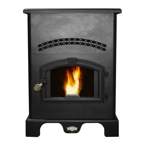
King/Ashley Pellet Stove
5500
Please read this entire manual before installation and use of this appliance. Failure to follow
these instructions could result in property damage, bodily injury, or even death.
Contact your local building or fire officials about obtaining permits, restrictions and installation
inspection requirements in your area.
Save these instructions.
Report #: 215-S-05b-2
"Keeping North America Warm Since 1869"
This unit is not intended to be used as a primary source of heat.
U.S. Environmental Protection Agency
Ce produit peut vous exposer à des produits chimiques, y compris le
Certified to comply with 2015 particulate emissions
monoxyde de carbone, qui est connu dans l'État de Californie pour causer
standards.
le cancer, des malformations congénitales et / ou d'autres problèmes de
reproduction. Pour plus d'informations, visitez www.P65warnings.ca.gov
CALIFORNIA PROPOSITION 65 WARNING:
This product can expose you to chemicals including carbon monoxide, which
is known to the State of California to cause cancer, birth defects and/or other
reproductive harm. For more information, go to www.P65warnings.ca.gov
UNITED STATES STOVE COMPANY • 227 INDUSTRIAL PARK ROAD
• SOUTH PITTSBURG, TENNESSEE 37380 • WWW.USSTOVE.COM
FOR TECHNICAL ASSISTANCE: PHONE: (800) 750-2723
5500XL
Models 5500/5500M/5500XL
5500M
851641P-4003H
Advertisement
Table of Contents

Related Manuals for United States Stove Company King/Ashley 5500XTL


Summary of Contents for United States Stove Company King/Ashley 5500XTL
- Page 1 This product can expose you to chemicals including carbon monoxide, which is known to the State of California to cause cancer, birth defects and/or other reproductive harm. For more information, go to www.P65warnings.ca.gov UNITED STATES STOVE COMPANY • 227 INDUSTRIAL PARK ROAD • SOUTH PITTSBURG, TENNESSEE 37380 • WWW.USSTOVE.COM 851641P-4003H...
-
Page 2: Safety Precautions
Safety Precautions This manual describes the installation and operation of the King/Ashley, 5500, 5500XL, 5500M wood heater. This heater meets the 2015 U.S. Environmental Protection Agency's crib wood emission limits for wood heaters sold after May 15, 2015. Under specific test conditions this heater has been shown to deliver heat at rates ranging from 9,126 to 27,677 Btu/hr. -
Page 3: Specifications
Specifications HEATING SPECIFICATIONS Fuel Burn Rate* 2.0 - 6.0 lbs./hr. (0.9 - 2.7 kg/hr) Burn Time (lowest setting) 5500/5500M - 60 hrs. 5500XL - 160 hrs. Hopper Capacity 5500/5500M - 120lbs. (55kg) 5500XL - 320lbs.(146kg) * Pellet size may effect the actual rate of fuel feed and burn times. Fuel feed rates may vary by as much as 20%. Use PFI listed fuel for best results. DIMENSIONS 5500/5500M 5500XL... -
Page 4: Do Not Burn
Installation This heater is designed to burn only PFI Premium grade pellets. This appliance can also burn pellets rated as standard after May 16, 2015 DO NOT BURN: 1. Garbage; 8. Railroad ties or pressure-treated wood; 2. Lawn clippings or yard waste; 9. -
Page 5: Floor Protection
FLOOR PROTECTION This unit must be installed on a non-combustible floor surface. If a floor pad is used, it should be UL listed or equal. The floor pad or non-combustible surface should be large enough to extend a minimum of 6 in. (152.4mm) in front, 6 in. (152.4mm) on each side, and 1 in. - Page 6 CLEARANCES Your pellet stove has been tested and listed for installation in residential, mobile home, and alcove applications in accordance with the clearances given in FIGURES 3-5 and TABLE 1. Clearances may only be reduced by means approved by the regulatory authority. NOTE: Distance “C”...
- Page 7 VENTING REQUIREMENTS Install vent at clearances specified by the vent manufacturer. Do not connect the pellet vent to a vent serving any other appliance or stove. Do not install a flue damper in the exhaust venting system of this unit. ...
-
Page 8: Pellet Vent Termination
PELLET VENT TERMINATION Do not terminate the vent in an enclosed or semi-enclosed area, such as; carport, garage, attic, crawl space, under a sundeck or porch, narrow walkway, or any other location that can build up a concentration of fumes. The termination must exhaust above the outside air inlet elevation. -
Page 9: Through The Wall Installation
THROUGH THE WALL INSTALLATION (RECOMMENDED INSTALLATION) Canadian installations must conform to CAN/CSA-B365. To vent the unit through the wall, connect the pipe adapter to the exhaust motor adapter. If the exhaust adapter is at least 18 in.(457mm) above ground level, a straight section of pellet vent pipe can be used through the wall. -
Page 10: Outside Air Supply
OUTSIDE AIR SUPPLY (optional, unless installing in a mobile home) Depending on your location and home construction, outside air may be necessary for optimal performance. Metal pipe (solid or flexible) must be used for the outside air installation. PVC pipe is NOT approved and should NEVER be used. -
Page 11: Understanding Your Stove
ber by the exhaust or draft fan must be maintain precisely. Too little air will result in a flame that is non-energetic y. If the fuel continues to flow with too little air for long enough, the burn pot will fill with too much fuel and the fire mother out. -
Page 12: Control Panel Overview
Control Panel Overview Turning the heater ON/OFF, as well as adjustments for the fuel feed rate and room fan speed are performed by pressing the appropriate button(s) on the control panel which is located on the lower left-hand side of your heater. This unit can be changed between an automatic operation or a manual operation. - Page 13 Thermostat Hook-Up Must Remove Jumper First Put female plug fittings on the lead wires to your low voltage thermostat. Plug one thermostat lead onto each of the terminal posts on the circuit board. The stove will now drop back to heat setting 1.
-
Page 14: Operation
Operation UNIT PREPARATION After carefully unpacking and reading the instructions for installing your stove, you will need to perform the following steps: • Attach the included spring handle to the door handle by screwing it on in a respective location. •... -
Page 15: Start-Up Procedure
START-UP PROCEDURE DO NOT USE CHEMICALS OR FLUIDS TO START THE FIRE - Never use gasoline, gasoline-type lantern fuel, kerosene, charcoal lighter fluid, or similar liquids to start or “freshen up” a fire in this stove. Keep all such liquids well away from the stove while it is in use. -
Page 16: Daily Operation
DAILY OPERATION The hopper and stove top will be hot during operation; therefore, you should always use some type of hand protection when refueling your stove. Never place your hand near the auger while the stove is in operation. This unit should be filled when the hopper level drops below 3-inches. -
Page 17: Maintenance
Maintenance Failure to clean and maintain this unit as indicated can result in poor performance and safety hazards. Unplug your stove’s electrical cord prior to removing the back panel or opening the exhaust system for any inspection, cleaning, or maintenance work. ... -
Page 18: Blower Motors
BLOWER MOTORS Clean the air holes on the motors of both the exhaust and distribution blowers annually. Remove the exhaust blower from the exhaust duct and clean out the internal fan blades as part of your fall start-up. PAINTED SURFACES Painted surfaces may be wiped down with a damp cloth. -
Page 19: Troubleshooting
Trouble Shooting Disconnect the power cord before performing any maintenance! NOTE: Turning the ON/OFF Switch to ”OFF” does not disconnect all power to the electrical components of the stove. Never try to repair or replace any part of the stove unless instructions for doing so are given in this manual. All other work should be done by a trained technician. -
Page 20: Display Indicators
Error Codes and Display Indicators Error Error Possible Code Description Causes Err1 The high limit temperature sensor • Inadequate ventilation. has tripped. • Room fan failure. • Exhaust Blockage. • Electrical Open in wiring. Err2 Stove ran out of fuel during normal •... - Page 21 Parts Diagram/List models 5500, 5500M & 5500XL Model 5500 Item Part No. Title Qty. 25490 Door Weldment 891166 Ceramic Glass 891188 Glass Retainer, Top 891186 Glass Retainer, Bottom 25517 Handle, Door 891168 Latch, Door 88082 3/4” Rope Gasket 4.3 ft 88087 Glass Gasket 3.75 ft...
- Page 22 Parts Diagram model 5500, 5500M and 5500XL Note: All repair parts (other than Cabinet Sides, Hopper Assy., and Door Assy.) are same for models 5500, 5500M and 5500XL.
- Page 23 Parts List model 5500/5500M/5500XL Item Part No. Title Qty. Item Part No. Title Qty. 86624 Burnpot Assembly 80473 Blower, Exhaust 86625 Housing Assy, Burnpot 88118 Gasket, Igniter Flange 86628 Weldment, Exhaust Duct 891169 Hose, Heater 1.5 in 86633 Weldment, Igniter Tube 891141 Auger 80619...
-
Page 24: Wiring Diagram
Wiring Diagram... -
Page 25: Service Record
Service Record Service Record It is recommended that your heating system is serviced regularly and that the appropriate Service Interval Record is completed. SERVICE PROVIDER Before completing the appropriate Service Record below, please ensure you have carried out the service as described in the manufacturer’s instructions. - Page 26 2. THE PART DESCRIPTION / LA DESCRIPTION DE LA PIÈCE ________________________________________________ 3. THE MODEL NUMBER / LE NUMÉRO DE MODÈLE _______________________________________________________ 4. THE SERIAL NUMBER / LE NUMÉRO DE SÉRIE ___________________________________________________________ United States Stove Company 227 Industrial Park Road P.O. Box 151...
- Page 28 BLANC NOIR BLANC ROUGE BLEU ORANGE...
Need help?
Do you have a question about the King/Ashley 5500XTL and is the answer not in the manual?
Questions and answers