Tuthill M-D Pneumatics PD Plus 17/46 Series Installation Operation Maintenance Repair Manual
Hide thumbs
Also See for M-D Pneumatics PD Plus 17/46 Series:
Table of Contents
Advertisement
M-D Pneumatics™
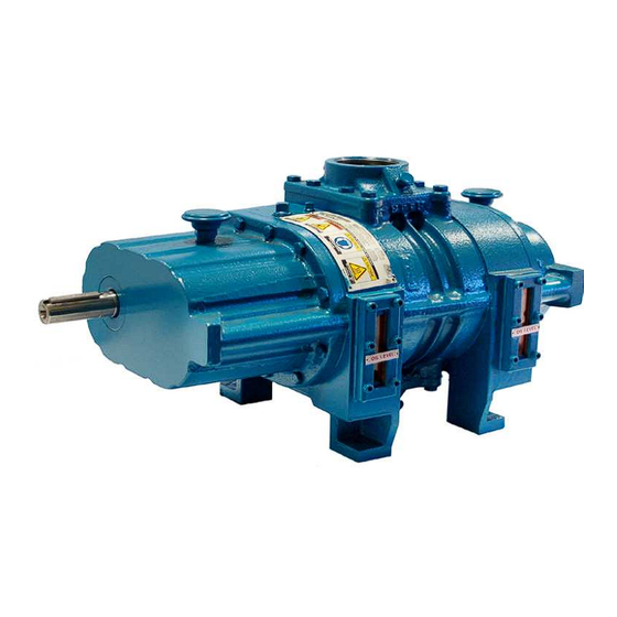
Rotary Positive Displacement Blower
Series 17/46 - Lip-Labyrinth (Air Service)
Series 57/81 - Single Envelope Gastight
Series 64/67 - Double Envelope Gastight
Models
3202
INSTALLATION
OPERATION
MAINTENANCE
REPAIR MANUAL
3204
3206
3210
4840 West Kearney Street, P. O. Box 2877
Springield, Missouri USA 65801-2877
Tel 417 865-8715 800 825-6937 Fax 417 865-2950
www.tuthillvacuumblower.com
Advertisement
Table of Contents
Troubleshooting

Subscribe to Our Youtube Channel
Related Manuals for Tuthill M-D Pneumatics PD Plus 17/46 Series


Summary of Contents for Tuthill M-D Pneumatics PD Plus 17/46 Series
- Page 1 M-D Pneumatics™ Rotary Positive Displacement Blower Series 17/46 - Lip-Labyrinth (Air Service) Series 57/81 - Single Envelope Gastight Series 64/67 - Double Envelope Gastight Models 3202 3204 3206 3210 INSTALLATION OPERATION MAINTENANCE REPAIR MANUAL 4840 West Kearney Street, P. O. Box 2877 Springield, Missouri USA 65801-2877 Tel 417 865-8715 800 825-6937 Fax 417 865-2950 www.tuthillvacuumblower.com...
-
Page 2: Table Of Contents
TABLE OF CONTENTS SECTION PAGE 1. INTRODUCTION 1.1 APPLICABLE DOCUMENTATION 1.2 SCOPE OF MANUAL 2. CONVENTIONS AND DATA PLATE 2.1 GRAPHIC CONVENTIONS IN THIS MANUAL 2.2 DATA PLATE 3. LIFTING 4. DESCRIPTION 4.1 FLOW BY DIRECTION 4.2 SPECIFICATIONS 5. INSTALLATION 5.1 GENERAL 5.1.1 LOCATION 5.1.2 FOUNDATION... -
Page 3: Introduction
® Tuthill Vacuum & Blower Systems. Please examine the blower for shipping damage, and if any damage is found, report it immediately to the carrier. If the blower is to be installed at a later date make sure it is stored in a clean, dry location and rotated regularly. -
Page 4: Data Plate
2.2 DATA PLATE MAWP YEAR Tuthill Vacuum & Blower Systems MAX RPM 4840 West Kearney Street Springfield, Missouri USA 65803 READ INSTRUCTION MANUAL BEFORE OPERATION OR BODILY HARM MAY RESULT... -
Page 5: Lifting
Refer to diagrams in this manual for proper rotation and orientation in inlet and discharge. Tuthill Vacuum & Blower Systems model 3200 Series rotary lobe blowers are positive displacement type units, whose pumping capacity is determined by size, operating speed, and differential pressure conditions. -
Page 6: Flow By Direction
Consult your Tuthill Vacuum & Blower Systems sales professional if questions arise. 4.1 FLOW BY DIRECTION... -
Page 7: Specifications
Specially ordered blowers with nonstandard construction, or with rotor end clearances greater than shown within the Assembly Clearances table, will not have the operating limits speciied here. Contact your Tuthill Vacuum & Blower Systems sales representative for speciic information. NOTE Special attention must be paid when a blower has a higher than standard ambient suction temperature. -
Page 8: Installation
5. INSTALLATION 5.1 GENERAL DANGER The blower is not intended to be used with explosive products or in explosive environments. The blower is not intended to be used in applications that include hazardous and toxic gases. Consult the factory for support. DANGER It is the responsibility of the installer to assure that proper guarding is in place and compliant with all applicable regulatory requirements. - Page 9 V-belt drive, to obtain other speeds within approved range. (See the Motor Drives section for more information.) Blowers from Tuthill Vacuum & Blower Systems are internally and externally treated after factory assembly and testing to protect PRESSURE...
-
Page 10: Location
opening the blower until ready to begin installation, as protection will be quickly lost due to evaporation. (For recommended preparations for long term storage (longer than 6 months), please see the Long Term Storage section in this manual.) 5.1.1 LOCATION Install your blower in a room or outdoor area that supplies adequate space and lighting for routine maintenance. -
Page 11: Safety
5.3 LUBRICATION Every booster from Tuthill Vacuum & Blower Systems is factory tested, oil drained and shipped dry to its installation point. Both independent oil reservoirs must be illed to the proper level before operation. Oil reservoirs are under vacuum. -
Page 12: Filling Procedure
Add oil to the booster in the quantity shown within the Speciications Table. The oil level must be maintained within the notched area of the sight glass. See Figure 5. Lower drive units have “bull’s eye” type oil level gauges. Maintain oil levels at the center of the glass. WARNING Never attempt to change or add lubrication while the booster is running. -
Page 13: Hazards Associated With Breakdown Or Ignition Of Lubrication
BREATHER 17/57/64 SERIES 46/81/67 SERIES AND OIL FILL HORIZONTAL FLOW VERTICAL FLOW (1) EACH OIL FILL END COVER PLUG (1) EACH NOTE: 64/67 SERIES END PLATE HAS PLUGS INSTEAD OF BREATHERS OIL FILL PLUG (1) EACH END PLATE OIL LEVEL GAUGE (1) EACH END PLATE... -
Page 14: Piping Connections
5.4 PIPING CONNECTIONS WARNING Pipe loading on the blower should be negligible as pipe loading can cause distortion of the blower. Use proper supports and pipe hangers to assure that there is no loading. NOTE Remove the protective covers from the inlet and outlet ports and inspect for dirt and foreign material. -
Page 15: Cooling Water Connections And Specifications - Cooling Coils (Optional)
Blowers supplied with coiling coils can also be identiied by the hose that connects the top of the gear (drive) end cover to the bottom of the free (non-drive) end cover. See Figures 6 and 7 for details. Tuthill Vacuum &... -
Page 16: Motor Drives
5.7 MOTOR DRIVES Two drive connections commonly used are direct drive and V-belt drive. 5.7.1 DIRECT COUPLED When installing the motor directly to the blower, align shafts to coupling in accordance with the coupling manufacturer’s instructions. Blowers shipped with motor directly coupled and mounted on a common base have been aligned prior to shipment and normally no further alignment is necessary. -
Page 17: Setting V-Belt Tension
5.7.3 SETTING V-BELT TENSION Proper belt tension is essential to long blower life. The following diagrams and procedures are provided to aid in ield adjusting V-belts (when blower is so equipped) for maximum performance. A visual inspection of the V-belt drive should yield the appearance shown in Figure 8. Factors outside the control of the belt tensioning system used on an individual blower package assembly may contribute to decreased belt life, such as environmental factors, and quality of the belts installed. -
Page 18: Special Instructions For Blowers With External Lubrication Systems
5.8 SPECIAL INSTRUCTIONS FOR BLOWERS WITH EXTERNAL LUBRICATION SYSTEMS Figure 10 - External Lube Oil Connections Blowers furnished with external lube systems are designated with a special series number after the model number; for example, 4009-84. On older units, it will appear before the model number. There are four variations manufactured: •... -
Page 19: Motor And Electrical Connections
5.9 MOTOR AND ELECTRICAL CONNECTIONS WARNING The motor and connections shall be protected to assure that product and environmental condensation does not come in contact with the electrical connections. NOTE It is the responsibility of the installer to assure that the motor is in compliance with the latest edition of IEC 60204-1 and all electrical connections performed per IEC 60204-1, this includes over current protection. -
Page 20: Start-Up Checklist
Initial operation should be carried out under “no load” conditions by opening all valves and venting the discharge to atmosphere, if possible. Then start motor briely, listen for unusual noises, and check that the blower coasts freely to a stop. If no problem appears, repeat this check, and let the motor run a little longer. If any questions exist, investigate before proceeding further. -
Page 21: Stopping
DANGER The blower is not intended to be used with explosive products or in explosive environments. The blower is not intended to be used in applications that include hazardous and toxic gases. Consult the factory for support. CAUTION Do not touch hot surfaces. The upper limit of the blower operation is 205º... -
Page 22: Water Injected Vacuum Or Pressure Blowers
However, due to the wide variations in mineral content, pH, and chemical content of water that can be injected, Tuthill Vacuum & Blower Systems cannot be responsible for damage which may result should this build-up occur. Units should be inspected regularly to determine any problems. -
Page 23: Maintenance
The following shutdown procedure outlined below minimizes the risk of moisture condensation, corrosion and freezing. NOTE Care must be taken so as not to overload or overheat the blower during this procedure. 1. Isolate the blower from the moist system piping, allowing the blower to intake atmospheric air. Operate the blower under a slight load allowing the blower to heat within safe limits. -
Page 24: Regular Maintenance
Personnel should have a good background of mechanical experience and be thoroughly familiar with the procedures outlined in this manual. Major repairs not covered in this book should be referred to the nearest Tuthill Vacuum & Blower Systems service representative. -
Page 25: Factory Service & Repair
7.4 FACTORY SERVICE & REPAIR With proper care, Tuthill Vacuum & Blower Systems blowers will give years of reliable service. The parts are machined to very close tolerances and require special tools by mechanics who are skilled at this work. -
Page 26: Model 3200 Disassembly And Reassembly
8. MODEL 3200 DISASSEMBLY AND REASSEMBLY 8.1 DISASSEMBLY OF BLOWER WARNING Before performing any repair or replacement, disconnect and lock out power. With proper maintenance and lubrication, normal life expectancy for gears, bearings, and seals can be achieved. However, over a period of time these parts must be repaired or replaced to maintain the eficiency of your blower. - Page 27 METHOD A: a. Place two hard wood or steel support blocks, 5½ to 6 inches (14 to 15 cm) high, on the bed of an arbor press. Set the unit, with the gears pointing down, on the two blocks making sure the blocks support the rotor housing only.
-
Page 28: Assembly Of Blower
Be sure they are in place. It is recommended that the gear end rotor shaft bearings be purchased from Tuthill Vacuum & Blower Systems, as they are specially ground to locate the rotors with correct end clearance relative to the gear end plate. - Page 29 10. Install spacer [17] (.260” [6.60 mm] thickness) and oil slinger [20] on the other shaft. NOTE Oil slinger and its spacer should always be mounted on either shaft for vertical low units. 11. Install timing shim in same location as found in disassembly. This does not necessarily insure the unit will be in proper time.
- Page 30 8.2.4 ADJUSTING ROTOR 2 LOBE LONG FEELER GAUGE INTERLOBE CLEARANCE RECORD A-A READING HERE 25. Lay the unit down with the drive gear RECORD B-B READING HERE on the left. Using feeler gauges take interlobe readings and record on each side of housing as indicated in Figure 13.
- Page 31 SPECIAL INSTRUCTIONS - 64/67 SERIES Continue assembly: A. Grease and install O-ring [140] into groove of seal adapter housing [91]. Press in stator portion (carbon) of mechanical seal [76]. B. Place a bead of silicone sealer around the periphery of the end plate and encircle each bolt hole. Install gear end cover [6], and secure with cap screws and washers [26A &...
-
Page 32: Troubleshooting
9. TROUBLESHOOTING Although Tuthill Vacuum & Blower Systems blowers are well designed and manufactured, problems may occur due to normal wear and the need for readjustment. The chart below lists symptoms that may occur along with probable causes and remedies. -
Page 33: Assembly Clearances
10. ASSEMBLY CLEARANCES Values shown in inches and millimeters. LOBES TO END PLATES LOBE TO HOUSING GEAR END FREE END TIP-PORT MODEL INTERLOBE .003 - .006 .004 - .009 .005 -.009 3202 .08 - .15 .10 - .23 .13 - .23 .003 - .006 .004 - .009 .005 -.009... -
Page 34: Recommended Lubricants
Blowers used in hydrogen service should use only PneuLube synthetic oil. Tuthill Vacuum & Blower Systems cannot accept responsibility for damage to seals, O-rings and gaskets caused by use of synthetic lubricants not recommended by Tuthill Vacuum and Blower Systems. -
Page 35: Special Tool Drawings
13. SPECIAL TOOL DRAWINGS FIGURE 15 — FIGURE 16 — 3200 SEAL PRESSING TOOL (T32018-1) 3200 SEAL PRESSING TOOL (T32018-2) 1.50 3.25 38.1 82.6 18.8 12.7 MIN R Ø 2.50 Ø 2.044 ± .001 Ø 1.872 ± .001 63.5 51.90 ± .03 47.55 ±... -
Page 36: Parts Lists And Assembly Drawings
PARTS LIST FOR MODEL 3200 SERIES - 17/46 ITEM 17/46 ITEM 17/46 PART DESCRIPTION PART DESCRIPTION ROTOR BREATHER HOUSING PORT FITTING END PLATE PORT FITTING GASKET DRIVE END COVER CAP SCREW FREE END COVER LOCK WASHER TIMING GEAR SET NAMEPLATE BEARING, DRIVE END DRIVE SHAFT BEARING, FREE END... - Page 37 PARTS LIST FOR MODEL 3200 SERIES - 57/81 ITEM 57/81 ITEM 57/81 PART DESCRIPTION PART DESCRIPTION BREATHER ROTOR HOUSING PORT FITTING CAP SCREW END PLATE LOCK WASHER DRIVE END COVER FREE END COVER NAMEPLATE DRIVE SHAFT TIMING GEAR SET BEARING, DRIVE END RETAINING RING BEARING, FREE END BEARING...
- Page 38 PARTS LIST FOR MODEL 3200 SERIES - 64/67 ITEM 64/67 ITEM 64/67 PART DESCRIPTION PART DESCRIPTION ROTOR LAB SEAL HOUSING MECHANICAL SEAL END PLATE SPACER DRIVE END COVER CAP SCREW FREE END COVER SPACER TIMING GEAR SET OIL GAUGE BEARING, DRIVE END SPACER BEARING, FREE END O-RING...
- Page 43 NOTES:...
- Page 44 NOTES:...
-
Page 45: Declaration Of Incorporation
17/46 — Lip-Labyrinth (Air Service) 57/81 — Single Envelope Gastight 64/67 — Double Envelope Gastight The person authorized compile the technical file is Xavier Lambert, Tuthill Corporation, Parc Industriel Wavre Nord-Avenue Vesale 30, B-1300 Wavre Belgium. Ron Rinke Director of Engineering, TVBS – Blower Systems Tuthill Vacuum &... -
Page 46: Warranty - Blower Products
WARRANTY – BLOWER PRODUCTS Subject to the terms and conditions hereinafter set forth and set forth in General Terms of Sale, Tuthill Vacuum & Blower Systems (the Seller) warrants products and parts of its manufacture, when shipped, and its work (including installation and start-up) when performed, will be of good quality and will be free from defects in material and workmanship. -
Page 47: Operating Data Form / Product Registration
NOTES: IMPORTANT All blowers manufactured by Tuthill Vacuum & Blower Systems are date coded at time of shipment. In order to assure you of the full benefits of the product warranty, please complete, tear out and return the product registration card below, or you can visit our product registration web page at: http://www.tuthillvacuumblower.com/index.cfm/contact-us/product-registration/... - Page 48 NO POSTAGE NECESSARY IF MAILED IN THE UNITED STATES BUSINESS REPLY MAIL FIRST-CLASS MAIL PERMIT NO. 2912 SPRINGFIELD MO POSTAGE WILL BE PAID BY ADDRESSEE ATTN. CUSTOMER SERVICE TUTHILL VACUUM & BLOWER SYSTEMS PO BOX 2877 SPRINGFIELD MO 65890-2150...
Need help?
Do you have a question about the M-D Pneumatics PD Plus 17/46 Series and is the answer not in the manual?
Questions and answers